Deep Beam Design – Direct Modeling(1)
Deep Beam – Design Specification
http://astruttie.aroad.co.kr/help/Tutorial1/AStrutTie-Tutorial-DeepBeam.html
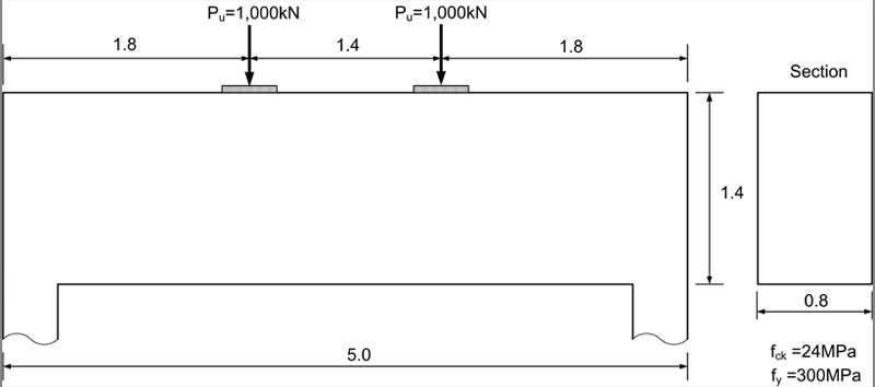
Let’s look at how to input and use the AStrutTie program through the design of deep beam using strut-tie model.
- Thickness : 0.800m
- fck : 24MPa
- fy : 300MPa
- Unit : kN.m
- Code : ACI 318-14
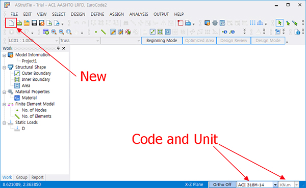
Creating Element
- Click [New]
- Set ACI 318-14
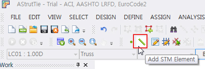
- Click [Add STM Element]
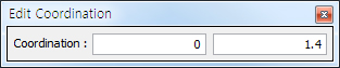
- Input coordinates (0, 0) and enter key. Move is possible with Tab key
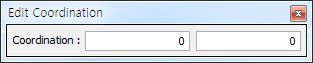
- Input coordinates (0, 1.400) and enter key
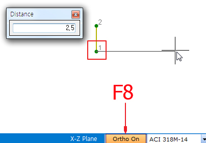
- Select on the bottom node (1) of the created member
- Click [F8] key , Ortho On
- Move the mouse horizontally and click any point
- [Distance] input 2.5m and enter key.
- Select the created horizontal member by dragging
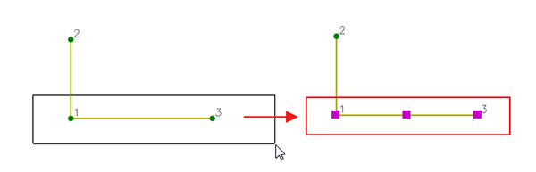
- [Ctrl + C], copy of element
- [Ctrl + V], paste of element
- Click on the upper node (2) of the vertical member as the reference point of the copied member
- Drag the top horizontal member that was copied
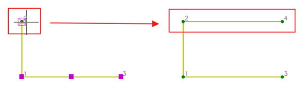
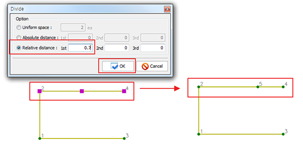
- Select upper element
- Click [Divide]
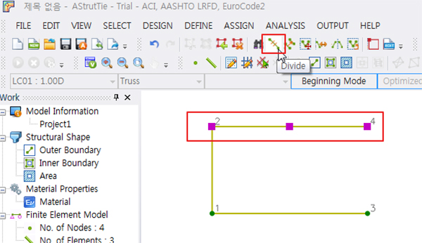
- Choose [Relative distance]
- 1st, input 0.7
- [OK]
- Select all members created by dragging
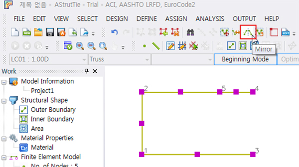
- Click [Mirror Node or Element]
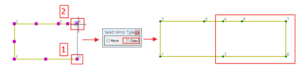
- Click on the upper right side joint and the lower right side joint of the member to specify the baseline
- [Select Mirror Type] dialog – choose [Copy]
Load Define and Loading
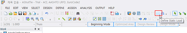
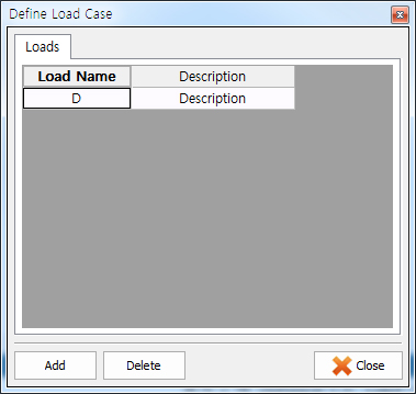
- 1. Load Define
- [Defind – Static Load]
- Load Name : Dead, Description : Description
- Click [OK]
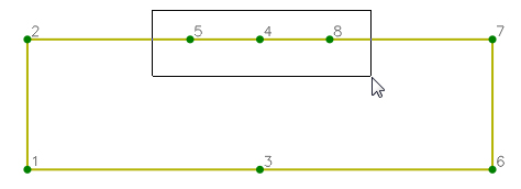
- 2. Loading
- Select two of the top of the absence by dragging
- Click [Assign – Static Load]
- Right-click on the left side of the load starting point
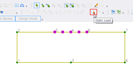
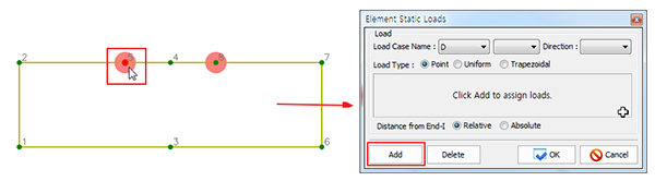
- After clicking Static Load, the Element Static Loads (Dialog) appears by clicking the right button of mouse
- when the color of node changes from green to red. And then, loads are assigned by clicking Add button.
- Click [Add]
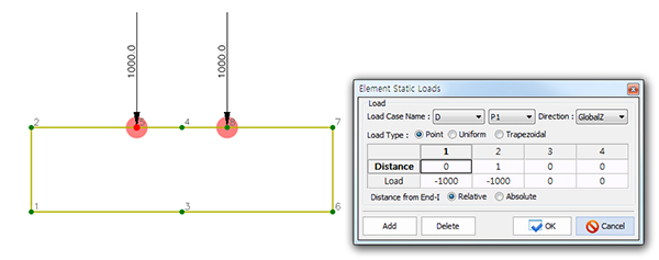
- Choose [Relative]
- 1 Distance:0.0, Load:-1000
2 Distance:1.0, Load:-1000
3, 4 Distance:0, Load:0
- [OK]
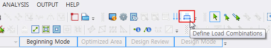
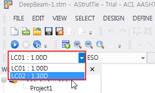
- Click [Defind – Load Combinations]
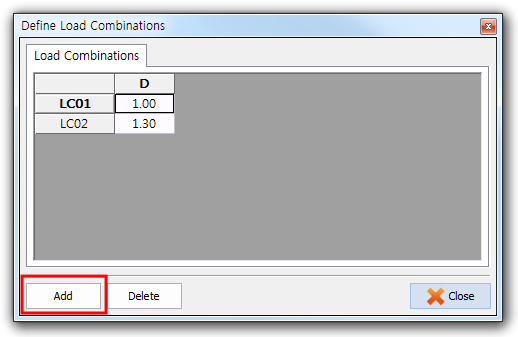
- Click [Add]
- LC01 : Dead=1.0, LC02 : Dead=1.3
- Click on the load in the Work Tree and check it on the screen.
- [save] – DeepBeam-1.stm
Make Structure and Area
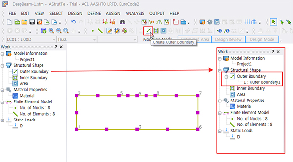
- 1. Make Structure
- Select all members created by dragging
- Design – [Create Outer Boundary] click
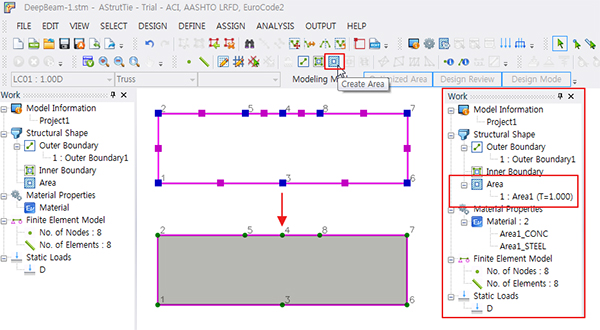
- 2. Make Area
- Select all members created by dragging
- Design – [Create Area] click
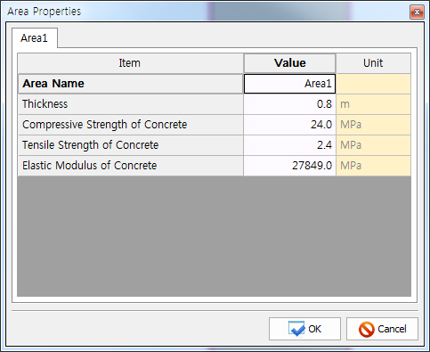
- Click [Defind – Area Properties]
- Thickness=0.800m
- Compressive Strength of Concrete (fck)=24MPa,
- Elastic Modulus of Concrete (Ec)=27,849MPa
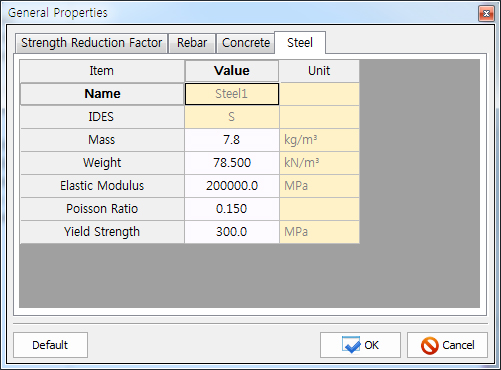
- Click [Defind – General Properties]-Steel Tab
- Yield Strength (fy)=300MPa,
- Elastic Modulus (Es)=200,000MPa
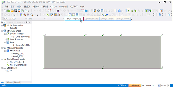
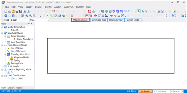
Modeling Mode
- Modeling Mode change
- Click [Beginning Mode] → Modeling Mode
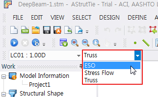
ESO
- Select [ESO] - The function is activated only in Professional Version.
- On Work tree, Load Combination : LC01 select to see load and modeling
- Select [LC02]
- On Work tree, Load Combination : LC02 select to see load and modeling
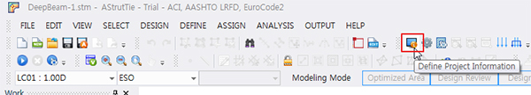
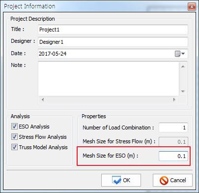
- Click [Project Information]
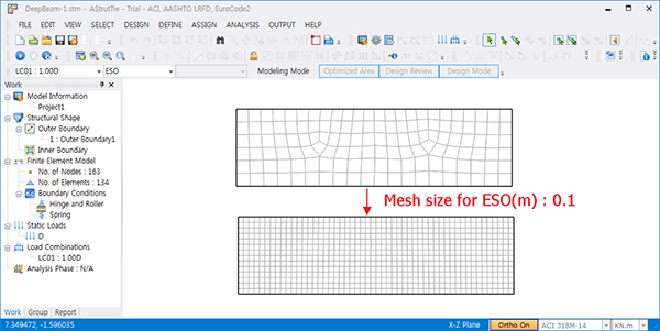
- Mesh size for ESO (m) : 0.1
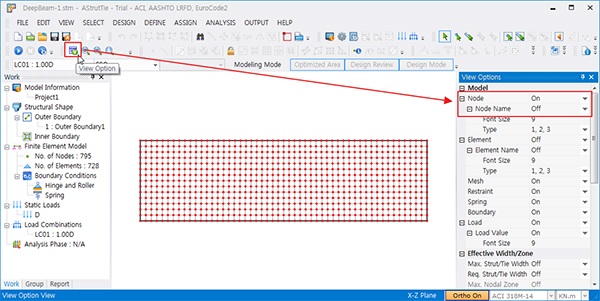
- Click [View Options]
- Node – On, Node name – Off
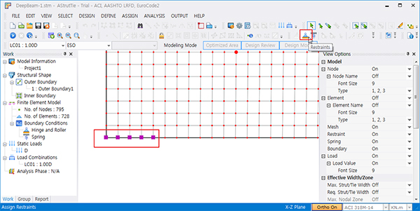
- Select 5 nodes on the bottom left
- Click [Assign Restraints]
- Set roller
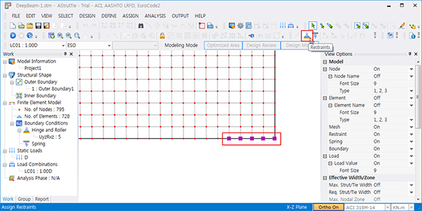
- Select 5 nodes on the bottom right
- Click [Assign Restraints]
- Set roller
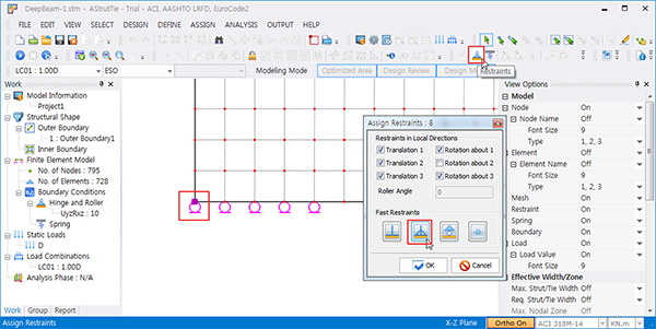
- Select the leftmost joint of the lower part
- Click [Assign Restraints]
- Set hinge
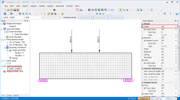
- Click [View Options]
- Node – Off
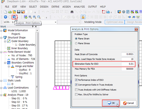
- Click [Analysis, Print Options]
- Elimination Ratio for ESO : 0.01 → [OK]
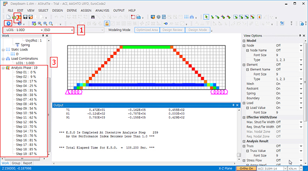
- Choose LoadCase : LC01 – 1
- Click [Run Model Analysis] – 2
- View ESO analysis result – 3
Stress Flow
- Tip : The work flow is almost the same as ESO, please refer to ESO.
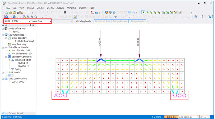
- Select [Stress Flow]
- On Work tree, Load Combination : LC01 select to see load and modeling
- Select [LC02]
- On Work tree, Load Combination : LC02 select to see load and modeling
- Project Information – Mesh size for Stress Flow (m) : 0.2
- VIEW – View Options Click
- Node – On
- Node name – Off
- Select 3 nodes on the bottom left
- [Assign Restraints]
- Set roller
- Select 3 nodes on the bottom right
- [Assign Restraints]
- Set roller
- Select the leftmost joint of the lower part
- [Assign Restraints]
- Set hinge
- [Run Model Analysis]
- http://astruttie.aroad.co.kr/help/Tutorial1/AStrutTie-Tutorial-DeepBeam.html