Deep Beam Design – Direct Modeling(2)
http://astruttie.aroad.co.kr/help/Tutorial1/AStrutTie-Tutorial-DeepBeam.html
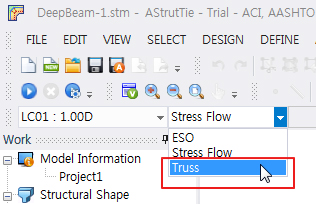
Truss
- Select [Truss]
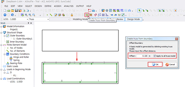
- Click [Create Truss From Boundary]
- Offset : 0.100 → [OK]
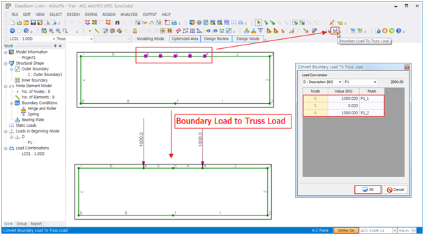
Load Assign
- View Option- Boundary Load : True
- Select two of the top of the absence by dragging
- Click [Boundary Load to Truss Load]
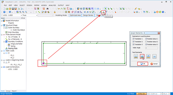
Set Restraint
- Select the leftmost joint of the lower part
- [Assign Restraints]
- Set hinge
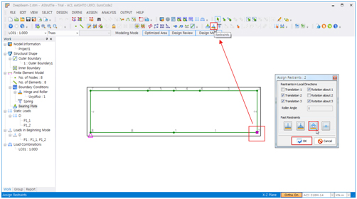
- Select the rightmost joint of the lower part
- [Assign Restraints]
- Set roller
Create Inner Element
- [Add Combined Shape] – The function is activated only in Professional Version.
- Select 2 Apply to left and right
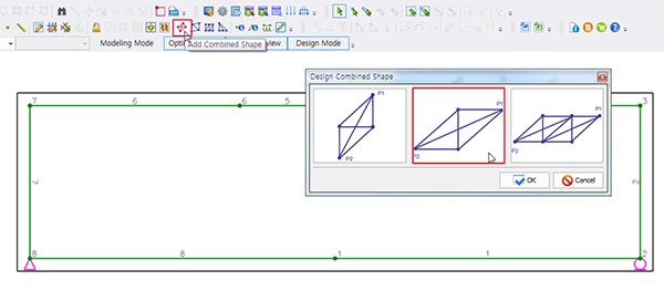
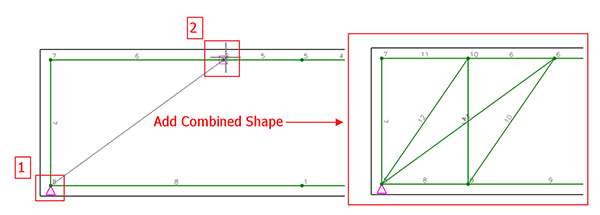
- Center-top, bottom member combination
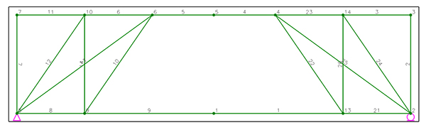
- Delete – Unnecessary element
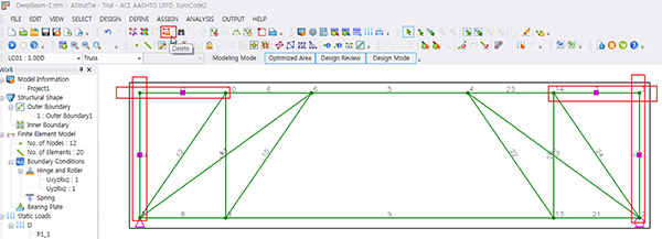
- Truss Modeling is complete.
Define Tie Types
- Truss members are all created and proceed to tie and strut member settings.
- Click [Define Reinforcement Ties]
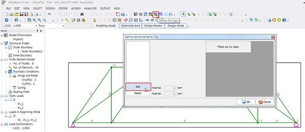
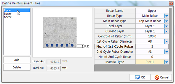
- Click [Add]
- Rebar Name = Upper
- Main Rebar Type = Top Main Rebar
- Centroid of Rebar (mm) = 100.0
- 1st Cycle Rebar Diameter = #8, No. of 1st Cycle Number = 8
- Click [Add]
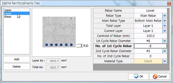
- Rebar Name = Lower
- Rebar Type = Main Rebar
- Main Rebar Type = Bottom Main Rebar
- Centroid of Rebar (mm) = 100.0
- 1st Cycle Rebar Diameter = #8
- No. of 1st Cycle Number = 8
- Click [Add]
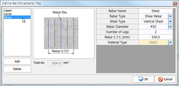
- Rebar Name = Shear
- Rebar Type = Shear Rebar
- Shear Type = Vertical Shear
- Diameter = #10
- Number of Legs = 2
- Rebar C.T.C (mm) =300
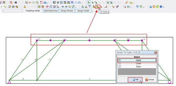
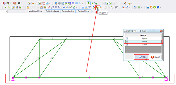
Assign Tie Types
- Select upper element
- Click [Assign Tie Type]
- Choose [Upper] → O.K
- Select bottom element
- Click [Assign Tie Types]
- Choose [Lower] → O.K
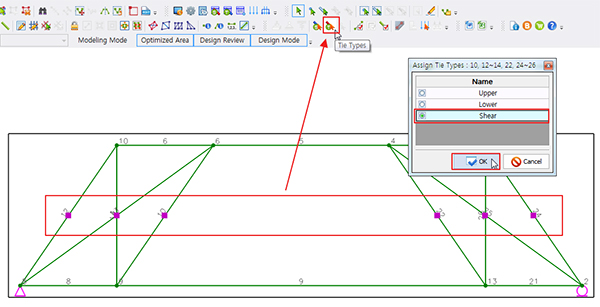
- Select center element
- Click [Assign Tie Types]
- Choose [Shear] → O.K
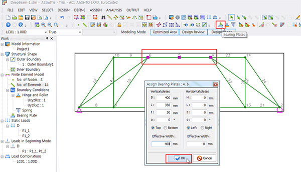
Bearing Plate
- Select load acting node
- Click [Assign Bearing Plates]
- Vertical plates
- B = 400mm, L = 350mm, T = 50mm, Effective Width = 400mm
- [OK]
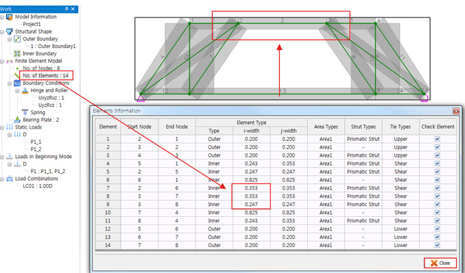
Max. Width and Outer Element
- Click [View Options]
- Max. Strut/Tie Width – On
- Click [Calculate Max. Width ]

- The available widths of all elements in a strut-tie model, calculated automatically by the program,
are displayed by executing the function DESIGN-Element Information or ASSIGN-Outer Element.
The available widths can be modified.
- Technical Reference
- The protrusion at the top is the max width considering the bearing plate.
- If you want to change the max width of a member, you can change it by two methods.
- The first is assign of Outer Element, the second is edit of Element Information.
- Reducing the maximum width with this function will result in a more secure design, but overshooting can be over-designed.
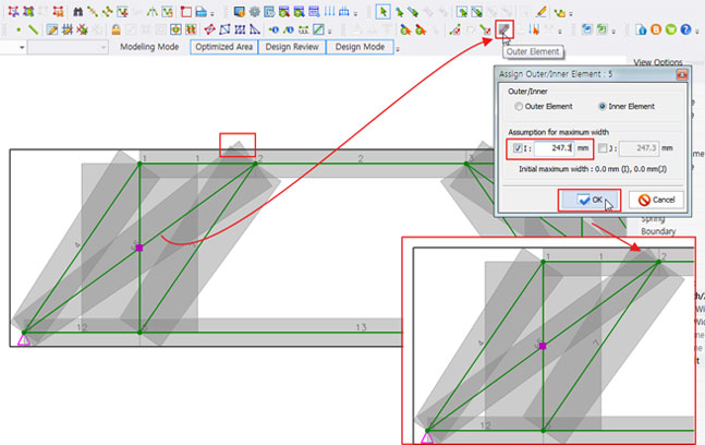
- Technical Reference – example
- Select Element 5
- Click [Outer Element]
- I : 247.3
- Click [OK ]
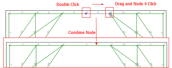
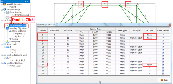
- Double Click [No. of Element]
- Element 7, I-Width : 0.353
- Element 8, I-Width : 0.353
- Element 9, I-Width : 0.247
- Click [Close ]
Assign Strut Types
- Select all element
- Click [Assign Strut Types]
- Choose [Prismatic Strut] → O.K
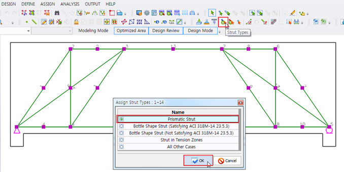
- Technical Reference
- In this example, all struts are set to Prismatic, but you can apply them differently at the designer’s discretion.
- An indeterminate truss will show different results depending on the selected strut type.
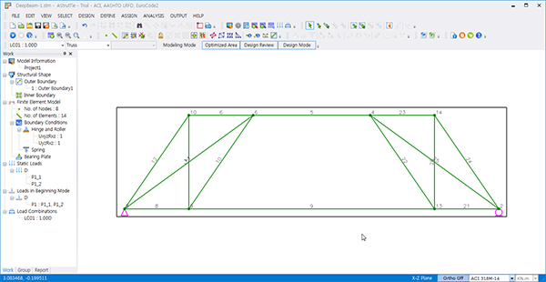
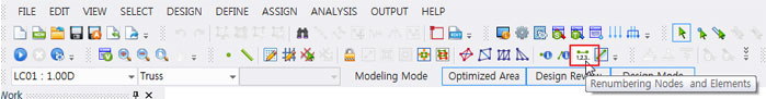
Truss Analysis and Design Review
- 1. Truss Analysis
- Click [Renumbering]
- Click [Run Analysis]
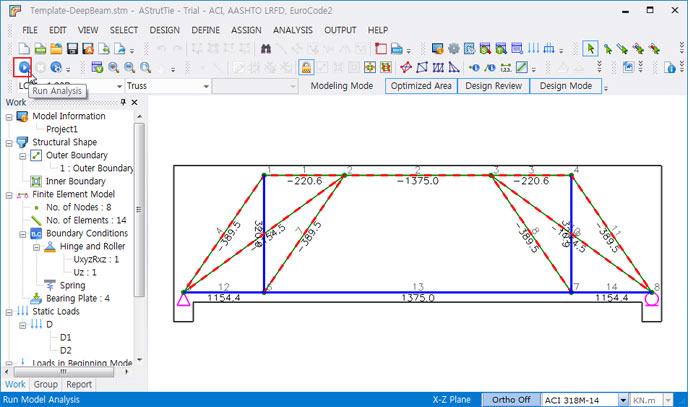
- 2. Design Review
- Click [Design Review]
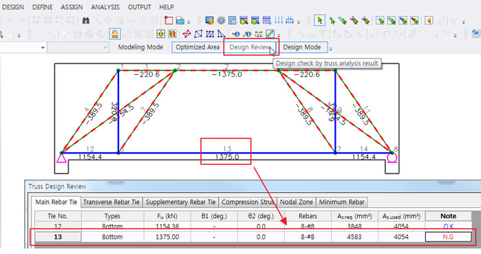
- Need to increase the amount of lower rebar.
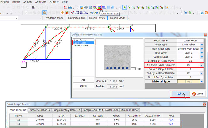
- Click [Define Reinforcement Ties]
- Lower 1st Cycle Diameter : #9 →[OK]
- Click [Design review]
- Main Rebar Tie is OK.
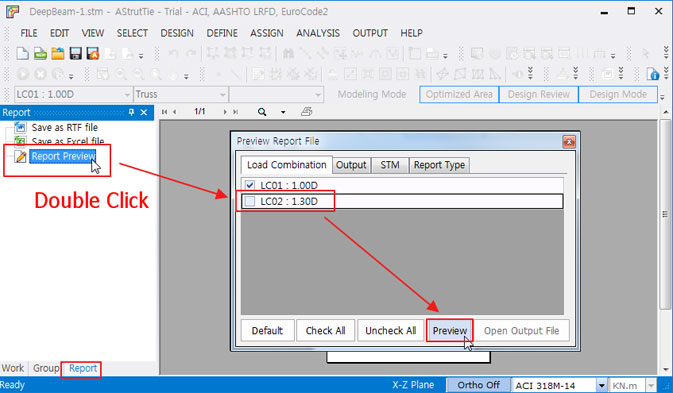
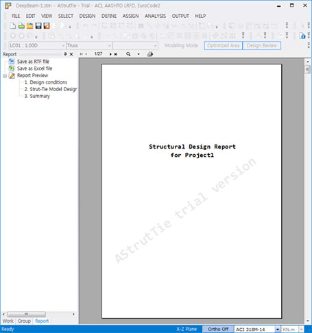
Report Preview and Save Report