| AStrutTie Design Step (2) – Application of Load |
|---|
| Writer | admin | Date | 2020.01.21 | Hit | 375 |
|---|---|---|---|---|---|
| File | |||||
Application of Load
Two methods for applying loads are provided in the program.
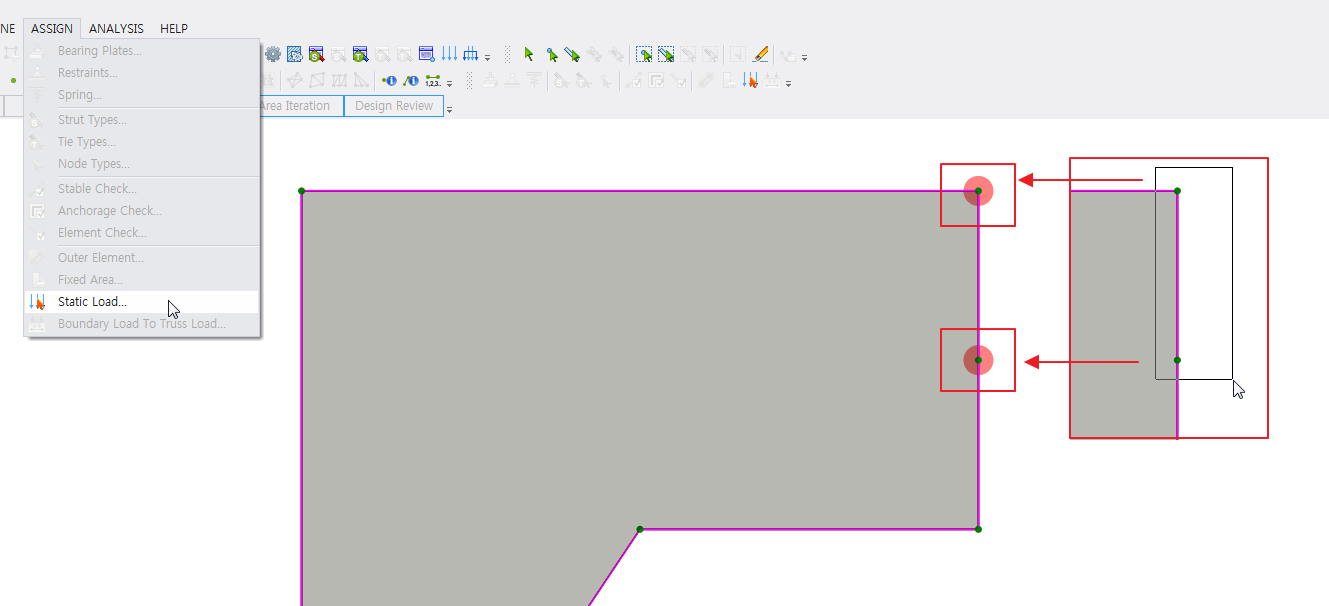
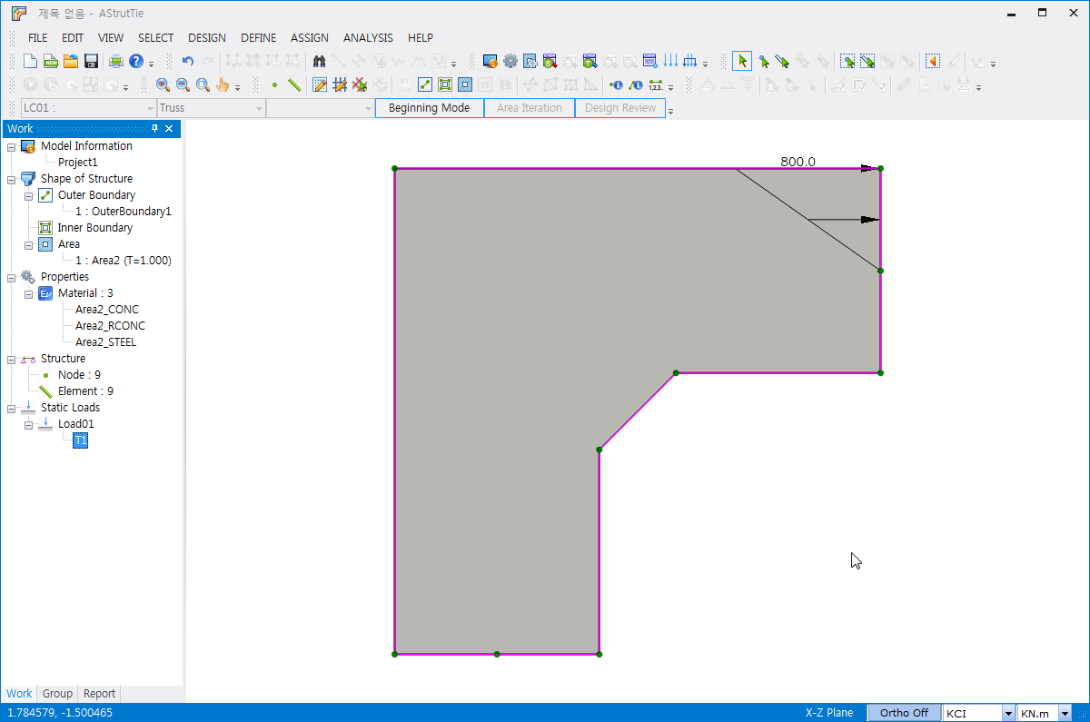
External loads are assigned by clicking ASSIGN-Static Load. After selecting nodes and elements, the following figure appears.
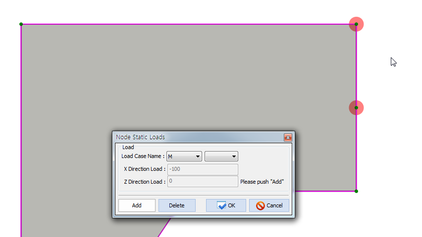
After clicking Static Load, the Node Static Loads (Dialog) appears by clicking the right button of mouse. And then, loads are assigned by clicking Add button.
2. Element Static Loads
After selecting nodes and elements, the following figure appears.

After clicking Static Load, the Element Static Loads (Dialog) appears by clicking the right button of mouse when the color of node changes from green to red. And then, loads are assigned by clicking Add button.
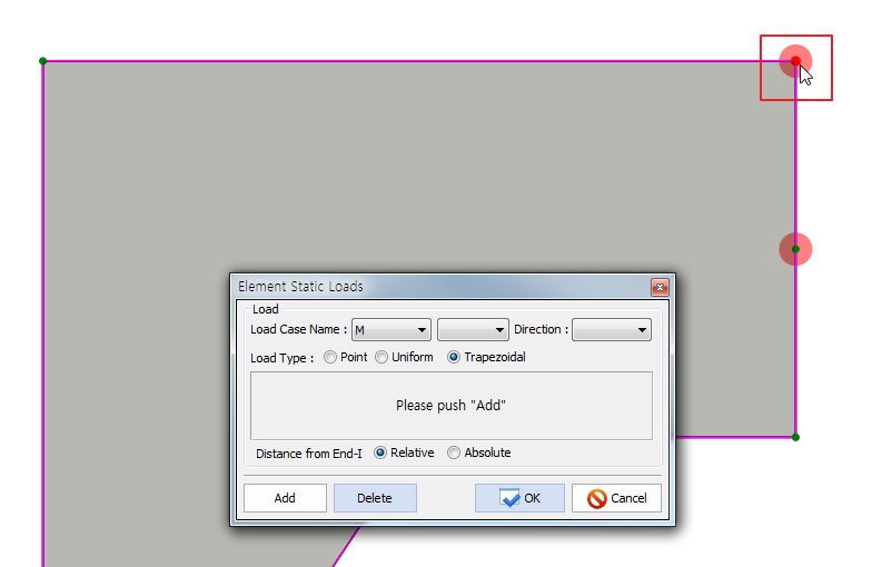
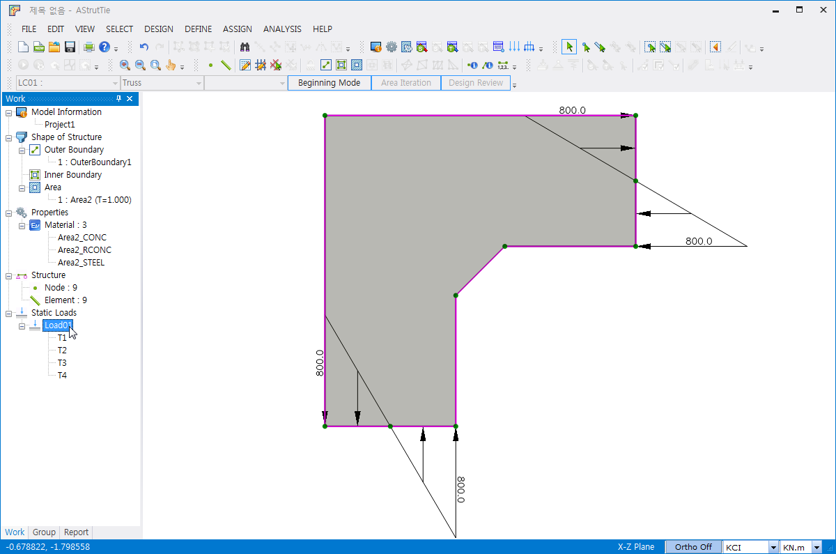
And then, the direction of load and load type must be selected. Three load types (point load, uniform load, and trapezoidal load) are available. An example for inputting trapezoidal load is shown below.
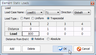
By repeating the inputting, multiple trapezoidal loads can be input as follows.
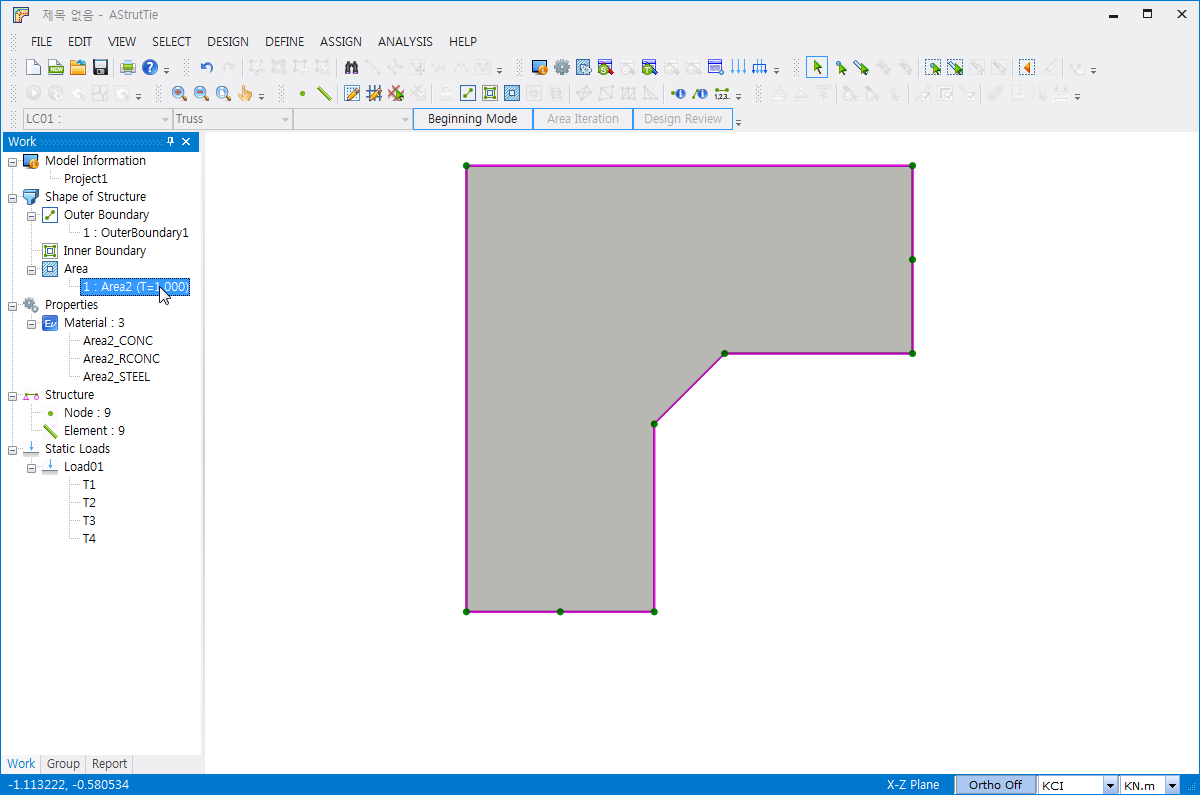
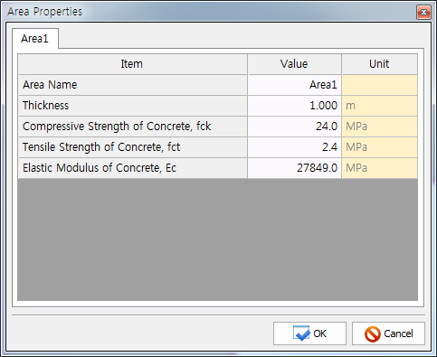
The material properties can be altered in Area Properties shown below.
| Prev | AStrutTie Design Step (3) – Structural Analysis for ESO & Stress Flow |
|---|---|
| Next | AStrutTie Design Step (1) – Modeling of Structure |