| AStrutTie Design Step (1) – Modeling of Structure |
|---|
| Writer | admin | Date | 2020.01.18 | Hit | 375 |
|---|---|---|---|---|---|
| File | |||||
1.1 Design Steps Using Strut-Tie Model
In the Beginning Mode, the design conditions of concrete member including the geometrical shape, load and boundary conditions, material properties, and load combinations are fixed. The design conditions are used in the Modeling Mode and design steps of strut-tie model method that require the finite element analysis of unreinforced plane concrete and truss structures.
1.2 Modeling of Member Geometry
The geometrical shape of concrete member is constructed in the Beginning Mode. The geometrical shape is constructed by 1) direct drawing, 2) importing a .dxf file, 3) using a Template. For direct drawing, the functions Add Nodes and Add Elements are used. The boundary lines and truss model of the concrete member are generated by importing a .dxf file. The geometrical shape, evolutionary structural optimization, stress flow, and truss model can be generated automatically by using a Template.
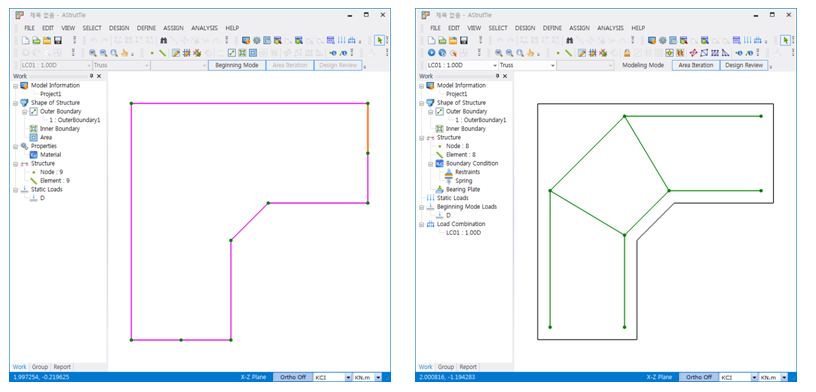
The geometrical shape of concrete member and truss model generated as .dxf files by using drawing tools including Autocad can be imported by clicking FILE-Import. In generating a .dxf file, all drawings must be constructed as lines, and the boundary of concrete member and truss model must be named as ‘Out’ and ‘Truss’ respectively.
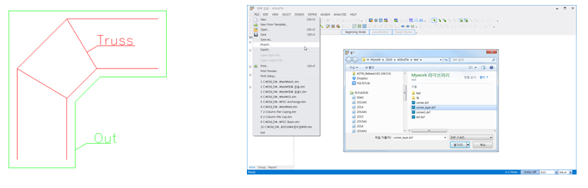
By importing a .dxf file, the boundary of concrete member and truss model are constructed automatically as follows.
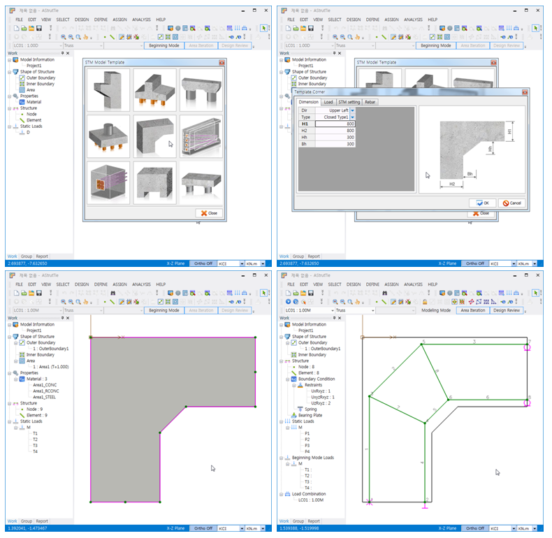
2. Use of Template
The geometrical shape of concrete member and truss model are generated by clicking FILE-New From Template and selecting one of the provided templates shown below. The basic information on the geometrical shape including thickness, width, and height must be input.
3. Direct Drawing
An example for constructing the boundary of concrete member is illustrated. The boundary can be constructed by using the functions Add Nodes or Add Elements. By clicking DESIGN-Add Elements, the coordinates of end points of lines are input in Edit Coordination (Dialog) as follows.
1.1 , 1.1 enter
1.9 , 1.1 enter
1.9 , 1.5 enter
1.9 , 1.9 enter
0 , 1.9 enter
0 , 0 enter
0.4 , 0 enter
0.8 , 0 enter
0.8 , 0.8 enter
1.1 , 1.1 enter
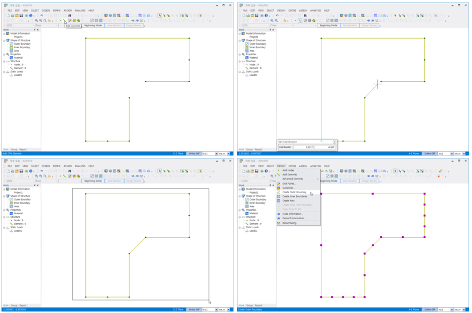
Once the boundary is constructed, the boundary must be recognized as the boundary of plane concrete member by clicking DESIGN-Create Outer Boundary.
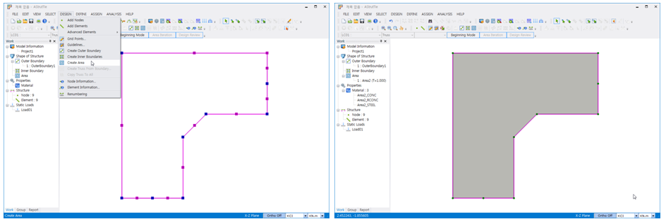
By clicking DESIGN-Create Area, the area surrounded by the outer boundary is set to designate the information of plane concrete member including member thickness, compressive strength of concrete, and yield strength of reinforcing bars.
| Prev | AStrutTie Design Step (2) – Application of Load |
|---|---|
| Next |