| Grid Strut-Tie Model – Max Widths of 2D |
|---|
| Writer | admin | Date | 2020.01.21 | Hit | 385 |
|---|---|---|---|---|---|
| File | Max-Widths-of-2D-02-3-599x381.png | ||||
The maximum width calculation method for evaluating the geometrical compatibility of grid strut-tie model.
The maximum widths of the horizontal and vertical elements are determined by taking 20% of the length of the neighboring vertical and horizontal elements respectively. The maximum widths of the inclined elements are taken as the lengths (Wd) of the perpendicular lines connecting the points (a, b, c, d), which are determined by considering the maximum widths of the neighboring horizontal and vertical elements (V1, V3, H1, H3). The reason for taking 20% of the lengths of the neighboring elements is based on a rule whereby the maximum widths of all elements in a square grid should be the same.
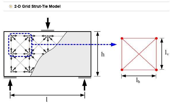
In a grid strut-tie model approach, a concrete strut is assumed to fail if its maximum width is less than the required width needed for carrying its cross-sectional force. Here, to reflect the actual characteristics of the load transfer mechanism within a grid, the modified maximum width of a concrete strut is used for examining the geometrical compatibility of a strut-tie model. The maximum width of the element increases as long as the required widths of the neighboring element B~E are less than their maximum load-carrying capacities (maximum widths). When the required widths of elements B~E is equal to zero, the modified maximum width of element A that can be maximized. This originated from the rule whereby the overlaps of widths of the neighboring elements are not allowed.
Appendix : Mathematical proof for taking 20% of the length of neighboring horizontal (vertical) components in the determination of the maximum width of vertical (horizontal) components
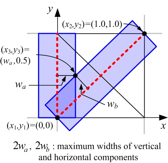
By using the equation of perpendicular, the half of the maximum width of the inclined plane component of the square grid element shown above is described as follows:
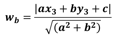
where the coefficients a, b, and c are a=y1-y2=-1.0, b=x2-x1=1.0, and c=x1y2-y1x2=0, respectively. Substituting the coefficients into above equation, we have

As the value 0.5 is the maximum half width that the vertical component can take, i.e., as wa=0.5, abs(-wa+0.5) becomes -wa+0.5. By using the condition that the halves of the maximum widths of the vertical and inclined components are the same, i.e., by equating wa to wb, we have

Therefore, the maximum width of the inclined plane component equals to those of neighboring vertical (horizontal) components if we take 20% of the length of neighboring horizontal (vertical) components.
Reference
| Prev | Grid Strut-Tie Model – Max Widths of 3D |
|---|---|
| Next | Grid Strut-Tie Model – Shear Wall with Openings |