| What is GSTM? |
|---|
| Writer | admin | Date | 2020.01.18 | Hit | 350 |
|---|---|---|---|---|---|
| File | blog_GSTM-01-1.png | ||||
A grid strut-tie model, composed of grids which are used to allow load transfers in all directions, is selected regardless of the stress trajectories and a designer’s subjectivity on stress flows.
The approach enables a structural design deliberating all kinds of load combinations by using a single type of grid strut-tie model.
A structural design is possible by using an indeterminate strut-tie model with appropriate element stiffness derived by applying a simple iterative technique to a grid strut-tie model.
Construction of Grid Strut-Tie Model
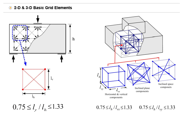
1. 2-D Grid Strut-Tie Model
A grid strut-tie model, composed of a number of grids, is selected by considering the loading and geometrical conditions of the structural concrete. A grid consists of four horizontal elements, four vertical elements, and four inclined elements, as shown in above figure. The ratio of vertical length to horizontal length of a grid is limited within the range of 0.75~1.33. If the ratio is not satisfied, the maximum width of an inclined element is reduced up to 90% of the width of the horizontal or vertical element, thus causing an improper load transfer capacity of the inclined element compared to the other elements.
2. 3-D Grid Strut-Tie Model
A 3-D grid strut-tie model is composed of a number of basic grid elements, and is constructed by considering the loading and geometrical conditions of the structural concrete. A basic grid element with twelve horizontal/vertical components, twelve inclined plane components, and four inclined space components is shown in above figure. The basic grid elements allow for load transfers in all directions at a node.
Application Procedure of the Grid Strut-Tie Model Approach
The analysis or design of 3-D structural concrete with D-regions using the proposed approach incorporating basic grid elements to construct a 3-D strut-tie model is conducted using the procedure shown in below figure.
A considerable amount of time and effort for determining the effective strengths and cross-sectional areas of struts and ties, and for examining the conditions of geometrical compatibility and nodal zone strength, is required in the proposed approach. In particular, the time and effort needed for numerous numerical calculations and graphical decisions are significantly increased when multiple load combinations are required. Therefore, we developed a computer graphics program to automate the design procedure, such as AStrutTie3D, by handling numerical calculations and graphical decisions effectively.
Reference
| Prev | Grid Strut-Tie Model – Shear Wall with Openings |
|---|---|
| Next |