| AStrutTie Design Step (4) – Modeling and Analysis of Truss Model |
|---|
| Writer | admin | Date | 2020.01.21 | Hit | 347 |
|---|---|---|---|---|---|
| File | |||||
Modeling and Analysis of Truss Model
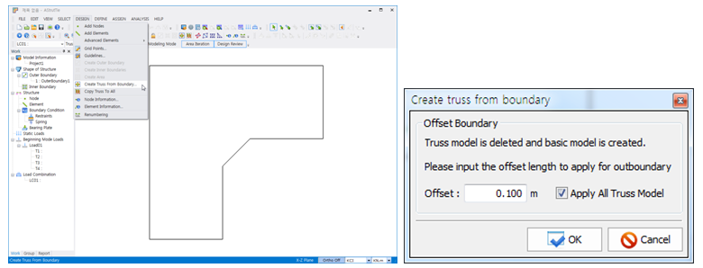
After the finite element analyses for the stress trajectories and evolutionary structural optimization, Truss Model need to be selected. The boundary elements of truss model are generated based on the outer boundary of concrete member by clicking DESIGN-Create Truss From Boundary (Dialog). In the dialog, the distance between the boundary of concrete member and the boundary elements of truss model is set.
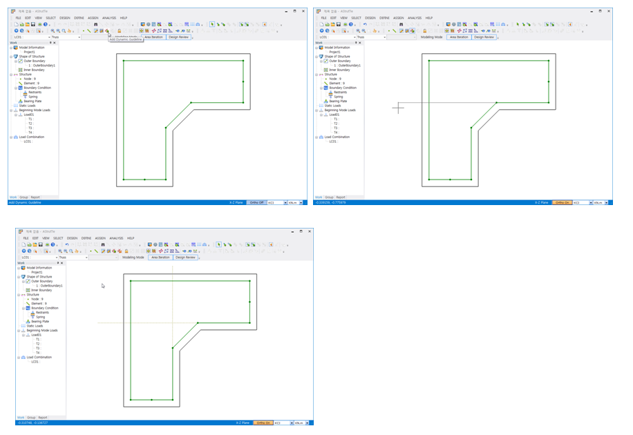
The boundary elements of truss model can be edited depending on designers’ decision. To make the editing easier, the functions Guide Line and Grid are provided. The orthogonal guide lines are available by clicking F8 key. An example to generate the boundary elements of truss model by clicking Dynamic Guide Line is shown below.
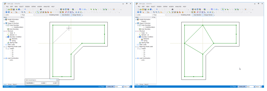
Based on the guidelines and by using Add Elements, additional elements of truss model are generated as shown below.
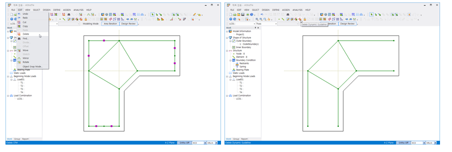
The unnecessary elements of truss model are deleted by using Del Key or Delete functions after selecting the elements.
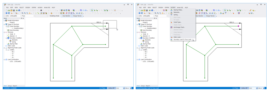
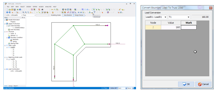
The external loads assigned in the Beginning Mode are converted to the loads acting on the generated truss model by clicking ASSIGN-Boundary Load To Truss Load. The loads on truss model can be input again by designers’ decision.
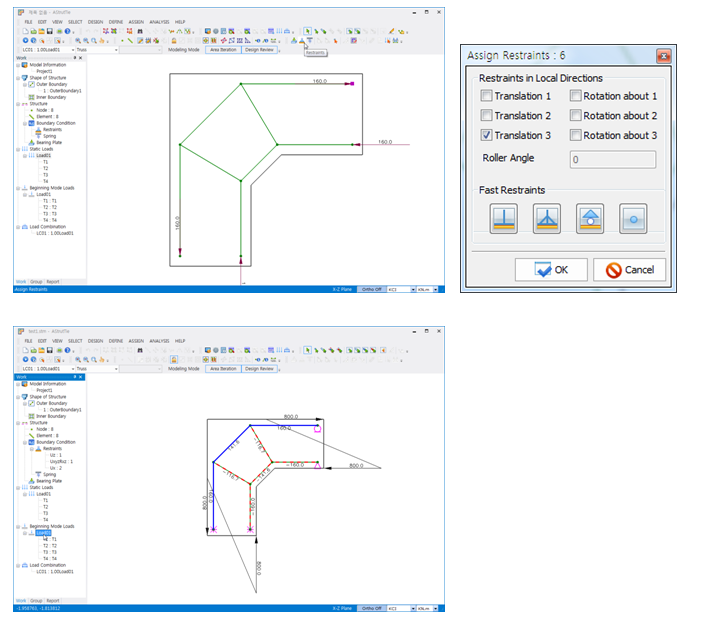
After selecting the nodes on which restraints must be imposed, the boundary conditions are setup by clicking ASSIGN-Restraints. The structural analysis on the truss model is conducted by clicking ANALYSIS-Run Analysis. After the analysis, the results including element forces are shown on the truss model.
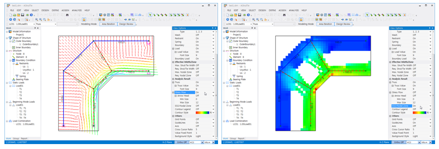
The compressive principal stress flows or the optimization results obtained earlier can be overlapped on the truss model by activating VIEW-View Options, as shown below.
| Prev | AStrutTie Design Step (5) – Analysis Results and Structural Design Report |
|---|---|
| Next | AStrutTie Design Step (3) – Structural Analysis for ESO & Stress Flow |