| Design of deep beams subjected to concentrated load (4) |
|---|
| Writer | admin | Date | 2020.01.22 | Hit | 605 |
|---|---|---|---|---|---|
| File | Design-*//Example-01.jpg01_Deepbeam_Combined_SI.stm | ||||
1.4 Design example – strut-tie model representing combined mechanism
1.4.1 Problem statement
In this section, the deep beam is designed by the strut-tie model representing the combined load transfer mechanism shown in Fig. 1-1(c). As illustrated in the previous sections, the dimensions and the information on the bearing plates and loads are determined in the same way.
1.4.2 Construction of strut-tie model
The ‘Beginning Mode’ is switched to the ‘Modeling Mode’ to construct a strut-tie model for the deep beam. As the shear span-to-effective depth ratio of the deep beam is 1.27, the indeterminate strut-tie model that represents a combined load transfer mechanism is selected automatically from the template for deep beam. In the model, the top and bottom horizontal elements are placed 127 mm and 102 mm away from the top and bottom surfaces of the deep beam, respectively.
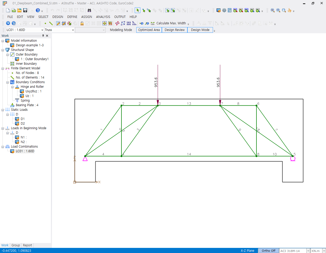
Fig. 1-10 Constructed strut-tie model
1.4.3 Analysis of strut-tie model
The cross-sectional forces of struts and ties are determined by carrying out the finite element analysis of the constructed strut-tie model. As the model is an indeterminate truss structure, an iterative procedure is employed to find the converged axial rigidities and cross-sectional forces of struts and ties.
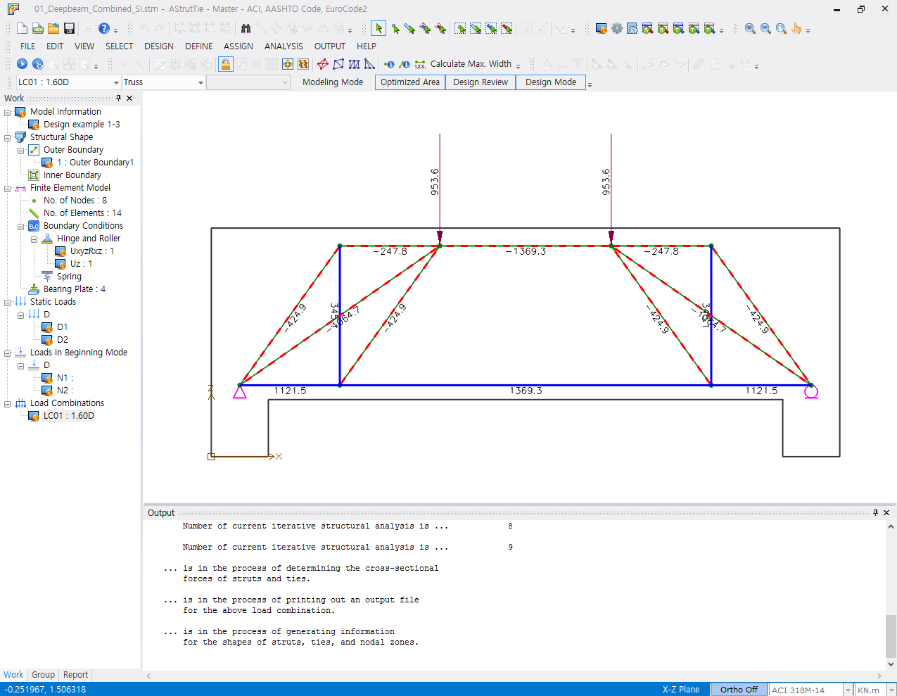
Fig. 1-11 Strut and tie forces
1.4.4 Strength verification and required rebars
1.4.4.1 Strength under bearing plates
The strength conditions under bearing plates are examined by the method illustrated in Section 1.2.4.1.
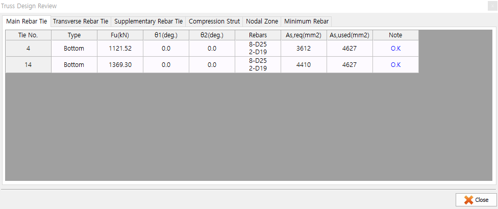
1.4.4.2 Required area of rebars
The required areas of main reinforcing bars are determined by the following equation. The requirement on the reinforcing bars is examined in the ‘Design Review’ as shown below.
As,req = Fu / φ fy (1-10)
where,
φ = strength reduction factor of steel tie (= 0.75)
Fu = cross-sectional force of steel tie
fy = yield strength of steel (= 414 MPa)
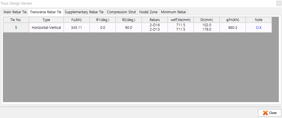
The spacing of shear reinforcing bars is determined by the following equation.
φFn = (φ Av fy weff,tie ) / sv ≥ Fu (1-11)
where,
φ = strength reduction factor of steel tie (= 0.75)
Av = area of vertical shear reinforcement
fy = yield strength of steel (= 414 MPa)
weff,tie = effective width of vertical tie (The half of the shear span is a default. A user can define the width in ‘Assign-Outer Element’)
Fu = cross-sectional force of steel tie
1.4.4.3 Strength verification of struts
The strength conditions of concrete struts are verified by comparing the required widths with provided (available) widths of concrete struts, as shown below.
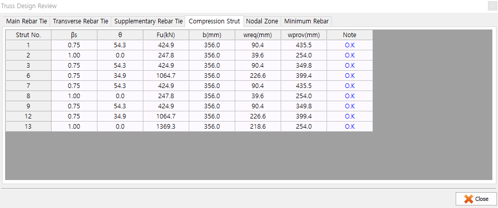
The strength conditions of concrete struts can also be verified visually as shown below.
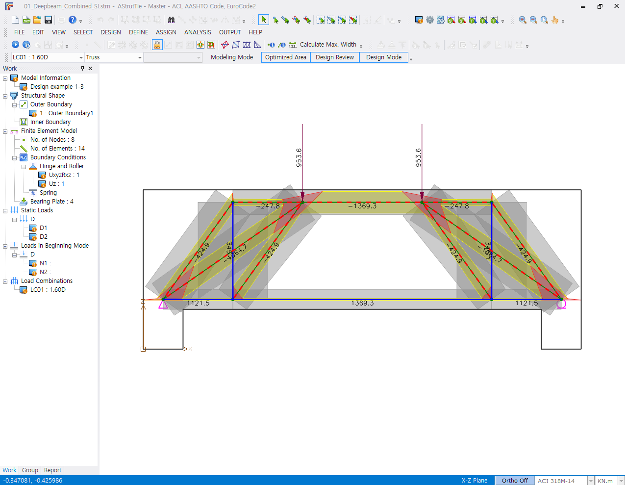
Fig. 1-12 Required/proposed area of concrete strut
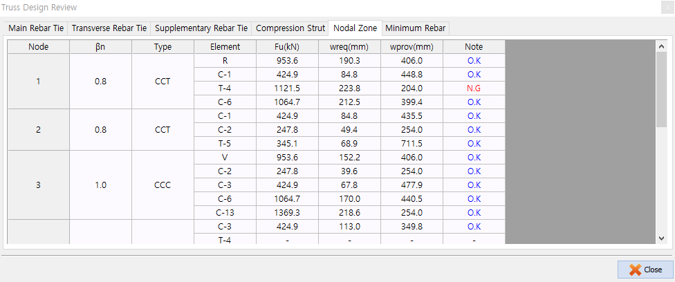
1.4.4.4 Strength verification of nodal zones
The strength condition of a nodal zone is verified by comparing the required width with the provided width of the nodal zone boundary, as shown below.
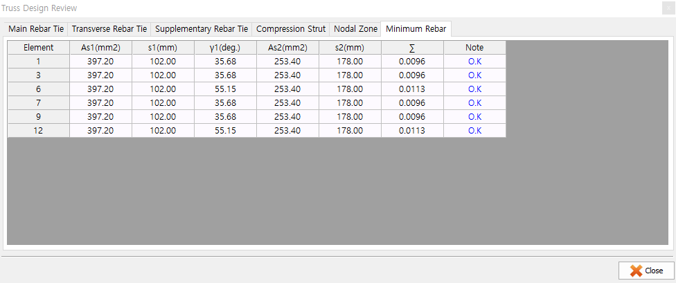
1.4.5 Minimum rebars for crack control
Since the effective strength coefficient 0.75 was taken for the two inclined struts of the strut-tie model, the ACI 318M-14 requirement for minimum reinforcing bars for crack control must be satisfied.
∑ (Asi / bssi) sin γi ≥ 0.003 (1-12)
where Asi is the total area of distributed reinforcement at spacing si in the i-th direction of reinforcement crossing a strut at an angle αi to the axis of a strut, and bs is the width of the strut.
| Prev | AStrutTie2020 Technical Book - Example 1 (Pier Coping) |
|---|---|
| Next | Design of deep beams subjected to concentrated load (3) |