| Design of deep beams subjected to concentrated load (2) |
|---|
| Writer | admin | Date | 2020.01.21 | Hit | 563 |
|---|---|---|---|---|---|
| File | Design-*//Example-01.jpg01_Deepbeam_Combined_SI.stm | ||||
1.2 Design example – strut-tie model representing arch mechanism
1.2.1 Problem statement
Design the simply supported deep beam that carries two concentrated factored loads of 953.6 kN (= 1.6 × 596 kN)each on a clear span of 3.66 m, as shown in Fig. 1-2. The deep beam has a thickness of 356 mm and a 1,220 mm overall depth. The length of the bearing plate at each concentrated load location is 406 mm and the width is the same as the beam thickness, i.e. 356 mm. Use fck = 27.6 MPa and fy = 414 MPa. Neglect the self-weight.
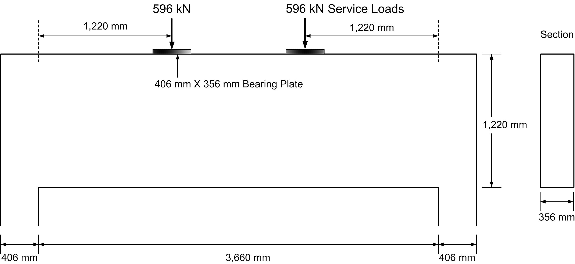
Fig. 1-2 Geometrical shape and loading conditions
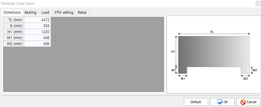
For the deep beam designs, a template provided in the AStrutTie can be used to make the designs easier. The template consists of five input tabs: Dimension, Bearing, Load, STM setting, Rebar. In the Dimension tab, the dimensions of the deep beam are typed in, as shown below.
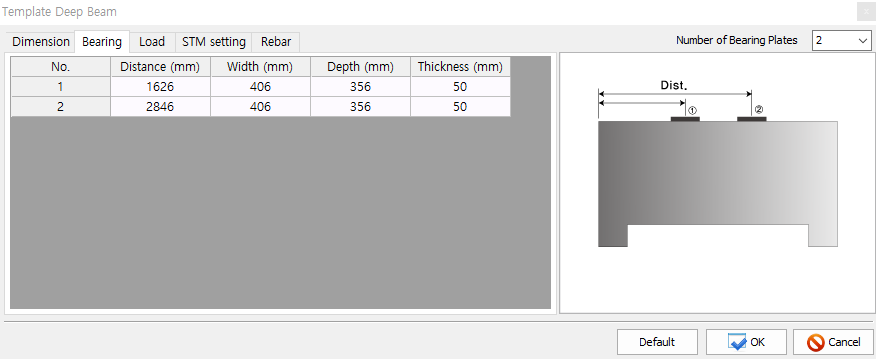
In the Bearing tab, the information on the bearing plates including the number of bearing plates, locations, width, depth, and thickness are typed in, as shown below.
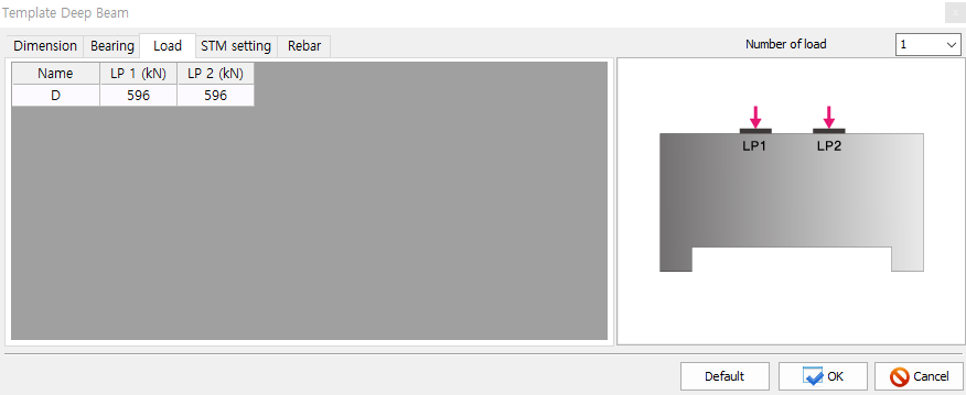
In the Load tab, the number of load types (dead load, live load, wind load, earthquake load, etc) and the magnitude of service loads are determined. The magnitude of loads can be modified in the later process.
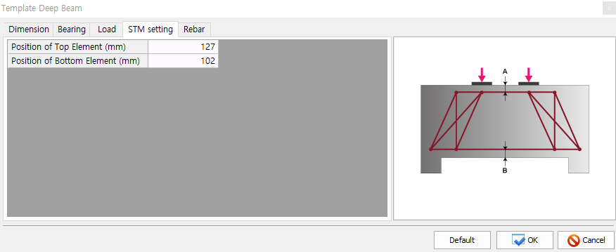
In the STM Setting tab, the locations of the top and bottom horizontal elements of the deep beam strut-tie model are assigned. The locations of the top and bottom elements are usually determined by considering the depth of the equivalent stress block and the effective depth of beam for flexure. In this example, the elements are placed 127 mm and 102 mm away from the top and bottom surfaces of the deep beam, respectively.
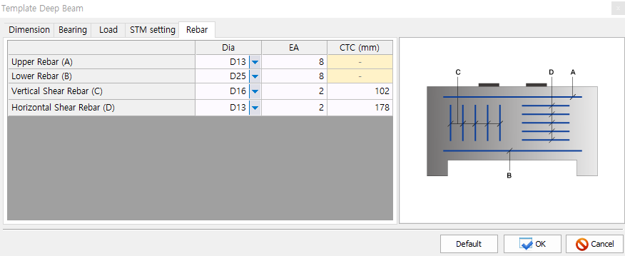
In the Rebar tab, the information on the reinforcing bars and details is assigned. The assigned information can be altered freely in the later process.
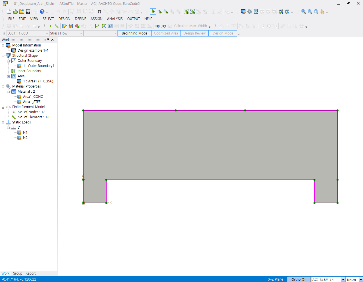
The ‘Beginning Mode’ is activated by clicking ‘OK’ button in the above window. All the entered information can be examined or modified in the Work Tree Window.
1.2.2 Construction of strut-tie model
To conduct the strut-tie model design of the deep beam, the ‘Beginning Mode’ must be switched to the ‘Modeling Mode’. The Modeling Mode consists of ESO, Stress Flow, Truss. As the template for deep beam is provided in the software, the most appropriate strut-tie model is constructed automatically. In this example, however, the finite element analyses for ESO and Stress Flow are carried out to illustrate the procedure for predicting the load transfer mechanisms of the deep beam.
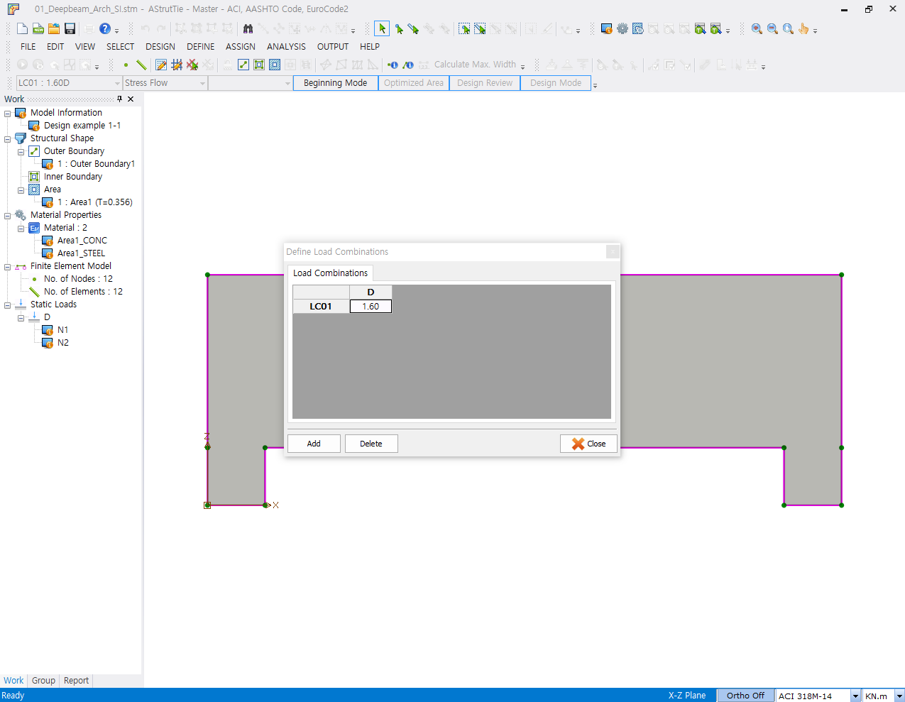
Before conducting the finite element analyses for ESO and Stress Flow, the load factor for live load, 1.6, is assigned in the ‘DEFINE-Load Combinations’.
The finite element analysis results are shown below.
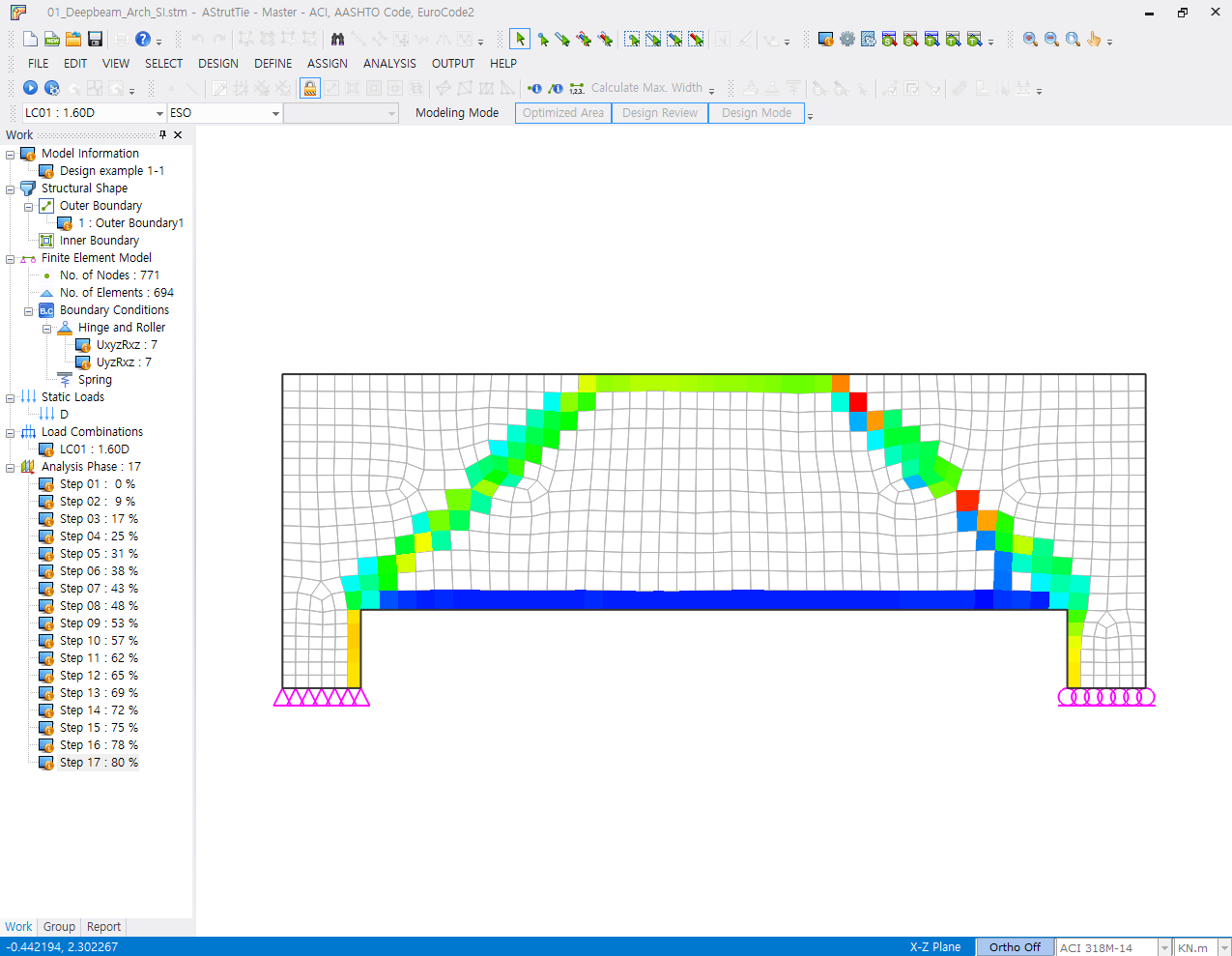
(a) Evolutionary structural optimization
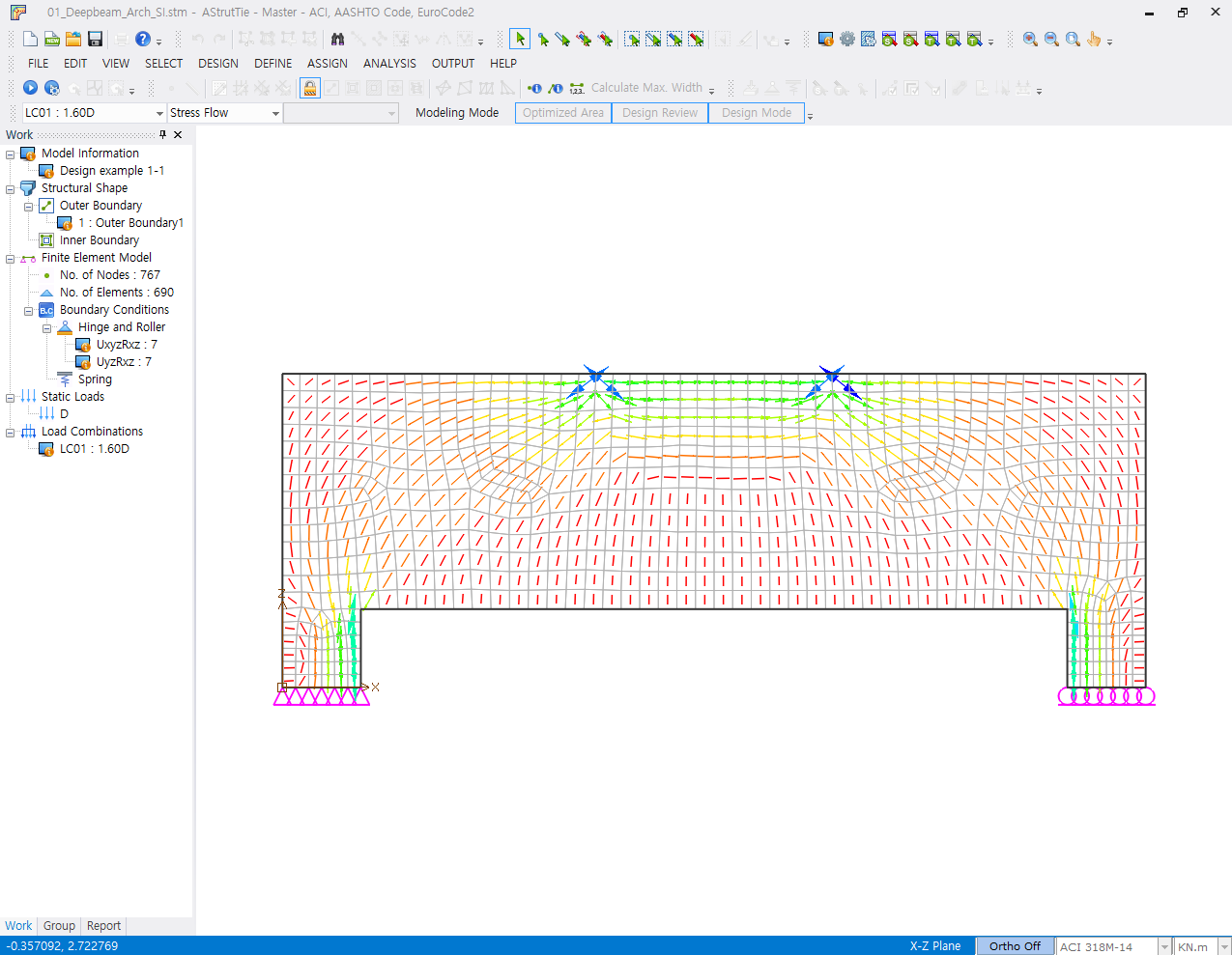
(b) Principal compressive stress flow
Fig. 1-3 Analysis results of ESO & Stress Flow
The strut-tie model for the deep beam is constructed by considering the principal stress flow and practical reinforcement patterns. When the template for deep beam is used, the strut-tie model representing a combined load transfer mechanism as shown in Fig. 1-1(c) is selected automatically as the shear span-to-effective depth ratio of the deep beam is 1.27. In this example, the strut-tie model representing an arch load transfer mechanism as shown in Fig. 1-4 is constructed for design. The top and bottom horizontal elements are placed 127 mm and 102 mm away from the top and bottom surfaces of the deep beam, respectively.
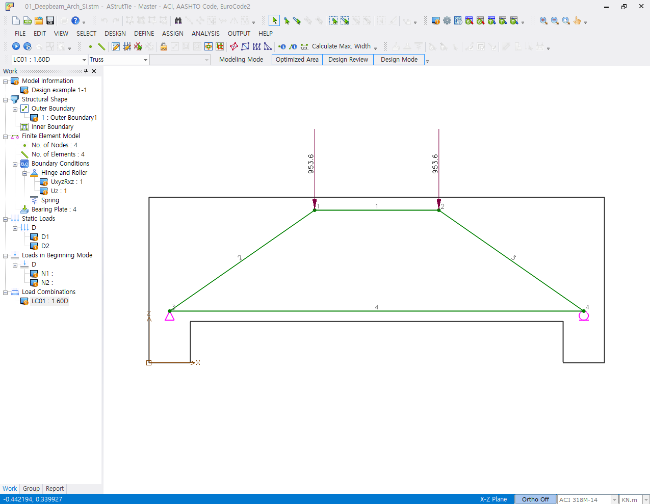
Fig. 1-4 Constructed strut-tie model
1.2.3 Analysis of strut-tie model
The cross-sectional forces of struts and ties are determined by carrying out the finite element analysis of the constructed strut-tie model.
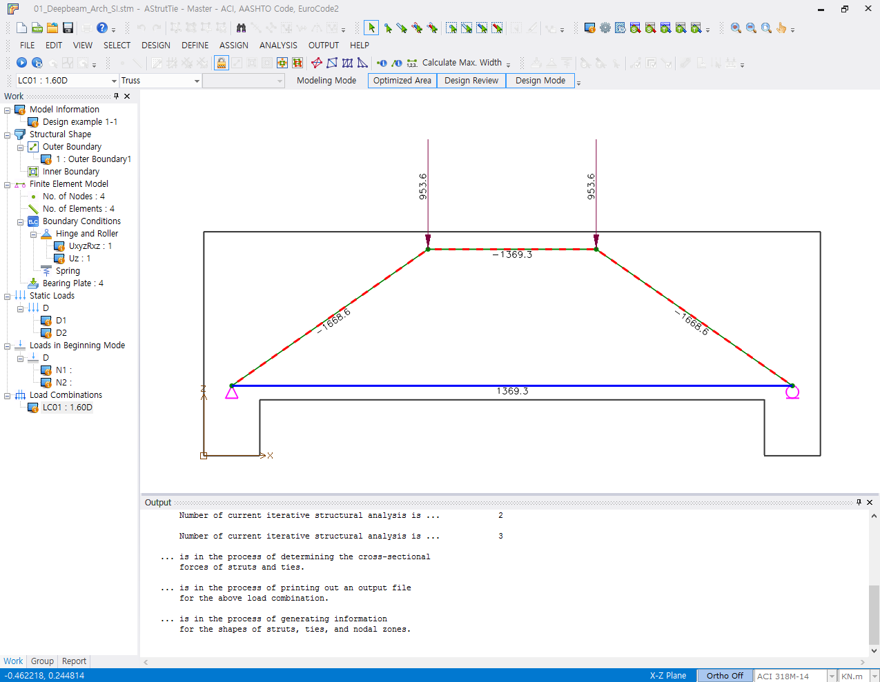
Fig. 1-5 Strut and tie forces
1.2.4 Strength verification and required rebars
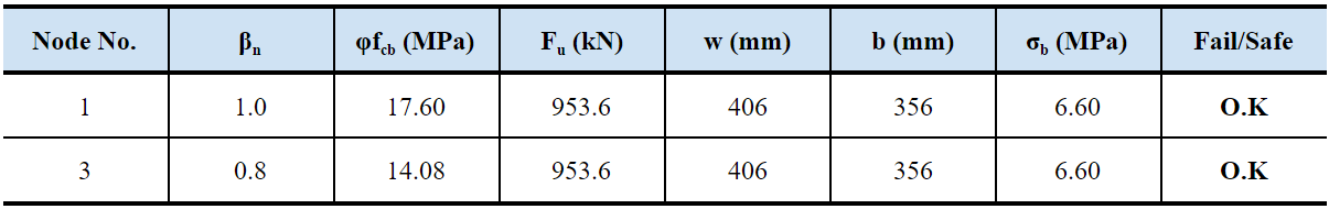
1.2.4.1 Strength under bearing plates
The strength conditions under bearing plates are verified by examining the following equation.
φfcb = φ 0.85βn fck ≤ Fu / bw = σb (1-2)
where,
φ = strength reduction factor of nodal zone (= 0.75)
βn = effective strength coefficient of nodal zone (CCC = 1.0, CCT = 0.8, CTT =0.6)
fck = compressive strength of concrete (= 27.6 MPa)
Fu = ultimate load acting on bearing plate
w = length of the bearing plate
b = width of the bearing plate
1.2.4.2 Required area of rebars
The required areas of main reinforcing bars are determined by the following equation. The requirement on the main reinforcing bars is examined in the ‘Design Review’ as shown below.
As,req = Fu / φfy (1-3)
where,
φ = strength reduction factor of steel tie (= 0.75)
Fu = cross-sectional force of steel tie
fy = yield strength of steel (= 414 MPa)
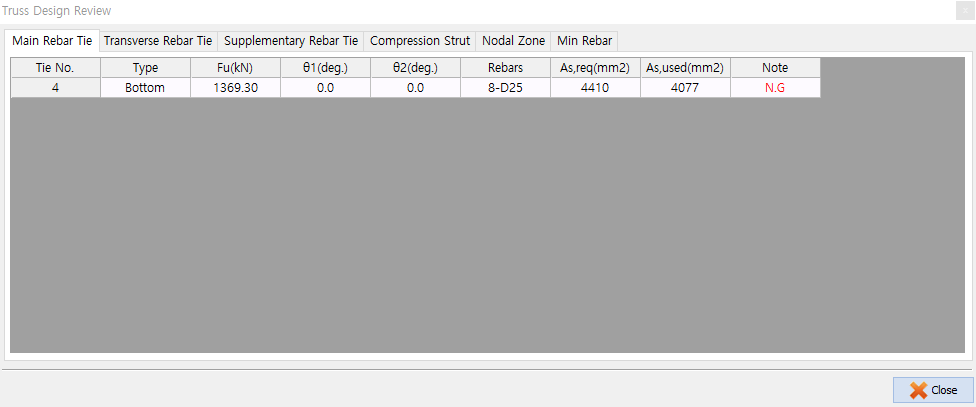
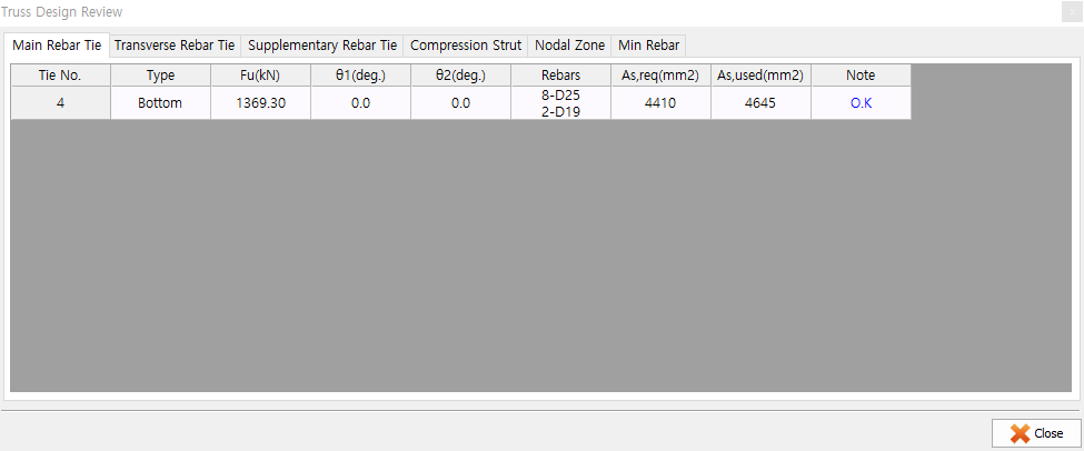
As shown above, the provided area of reinforcing bars (8-D25, 4,077 mm2) is not enough to carry the cross-sectional force of steel tie. Thus, 2-D19 bars are added in the ‘Define-Reinforcement Ties’.

After additional placement of reinforcing bars, the requirement on the main reinforcing bars is satisfied as shown below.
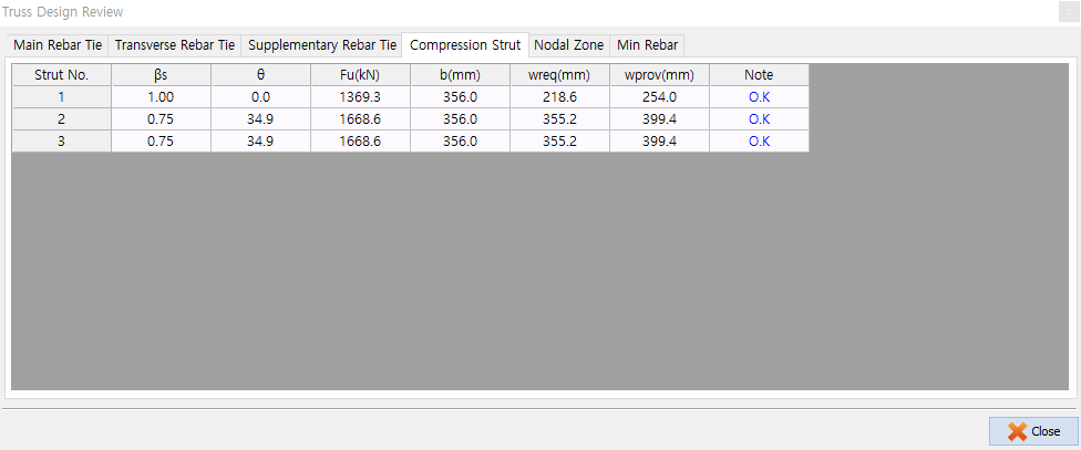
1.2.4.3 Strength verification of struts
The strength condition of a concrete strut is verified by comparing the required width with provided width of the concrete strut, as shown below.
wreq = Fu / (φ 0.85βs fck b) ≤ wprov (1-4)
where,
φ = strength reduction factor of concrete strut (= 0.75)
βs = effective strength coefficient of concrete strut
fck = compressive strength of concrete (= 27.6 MPa)
b = width of the beam
The strength conditions of concrete struts can also be verified visually as shown below.
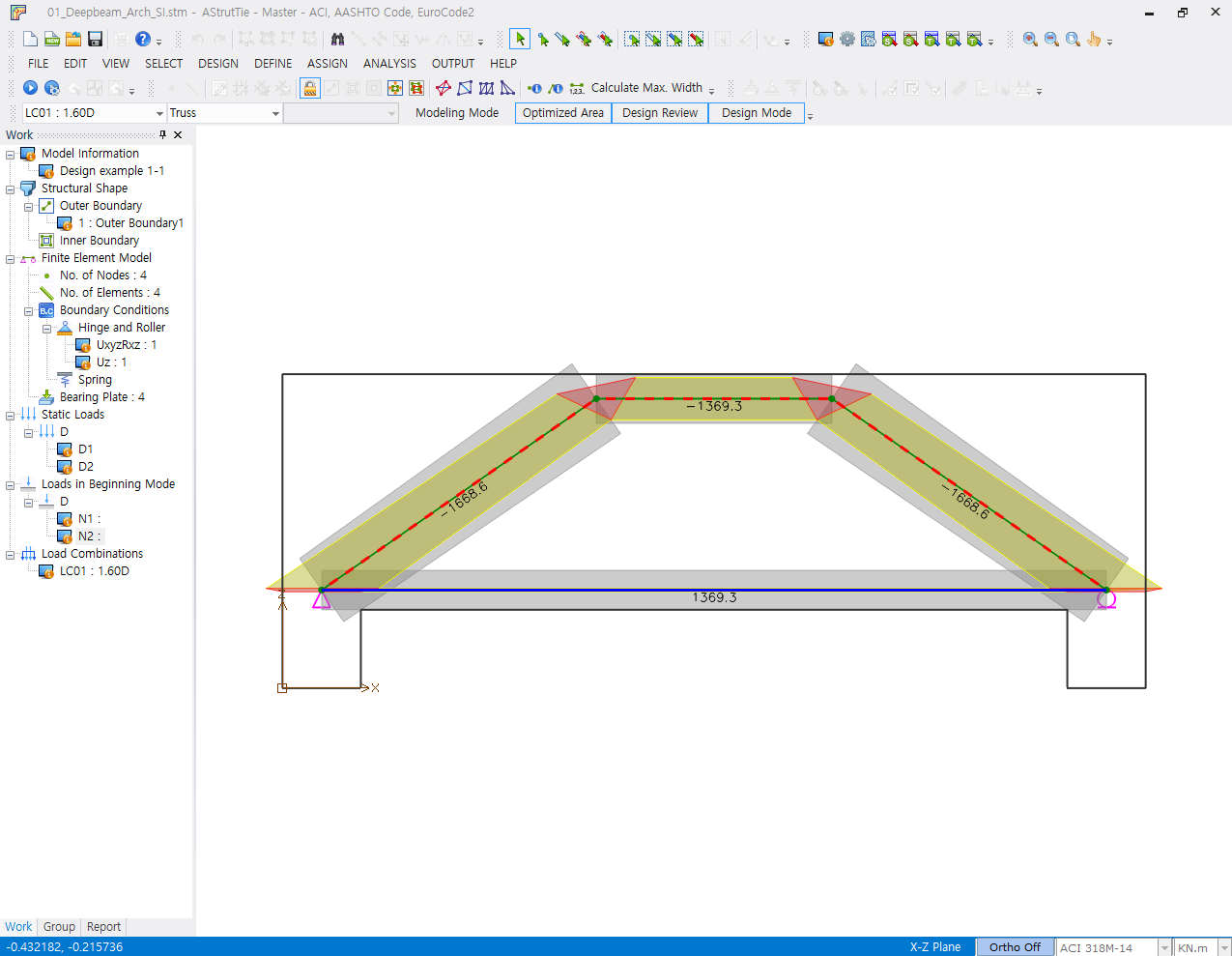
Fig. 1-6 Required/proposed area of concrete strut
1.2.4.4 Strength verification of nodal zones
The strength condition of a nodal zone is verified by comparing the required width with the provided width of the nodal zone boundary, as shown below.
wreq = Fu / (φ 0.85βn fck b) ≤ wprov (1-5)
where,
φ = strength reduction factor of nodal zone (= 0.75)
βn = effective strength coefficient of concrete strut
fck = compressive strength of concrete (= 27.6 MPa)
b = width of the beam
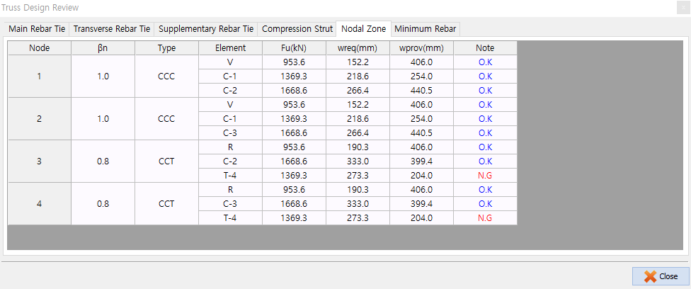
As shown in the above table, the strength condition about the nodes 3 and 4 is not satisfied. To satisfy the strength condition, the available width of horizontal lower tie must be increased by moving the tie upwards.
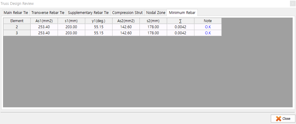
1.2.5 Minimum rebars for crack control
Since the effective strength coefficient 0.75 was taken for the two inclined struts of the strut-tie model, the ACI 318M-14 requirement for minimum reinforcing bars for crack control must be satisfied.
∑ (Asi / bssi) sin γi ≥ 0.003 (1-6)
where Asi is the total area of distributed reinforcement at spacing si in the i-th direction of reinforcement crossing a strut at an angle αi to the axis of a strut, and bs is the width of the strut.
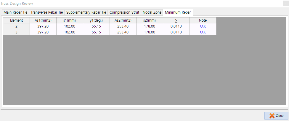
As shown in the above table, the assigned amounts of reinforcing bars are well above the required. The reinforcing bars can be reduced in the ‘Define-Reinforcement Ties’ menu.
| Prev | Design of deep beams subjected to concentrated load (3) |
|---|---|
| Next | Design of deep beams subjected to concentrated load (1) |