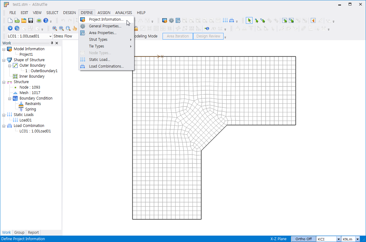
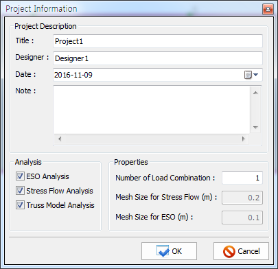
The window transforms to the Modeling Mode for numerical structural analysis after imposing loads on a concrete member. The Modeling Mode consists of ESO, Stress Flow, and Truss. The finite element model of a concrete member for ESO and Stress Flow analyses is constructed by using a mesh generator. The mesh size is setup by clicking DEFINE-Project Information.
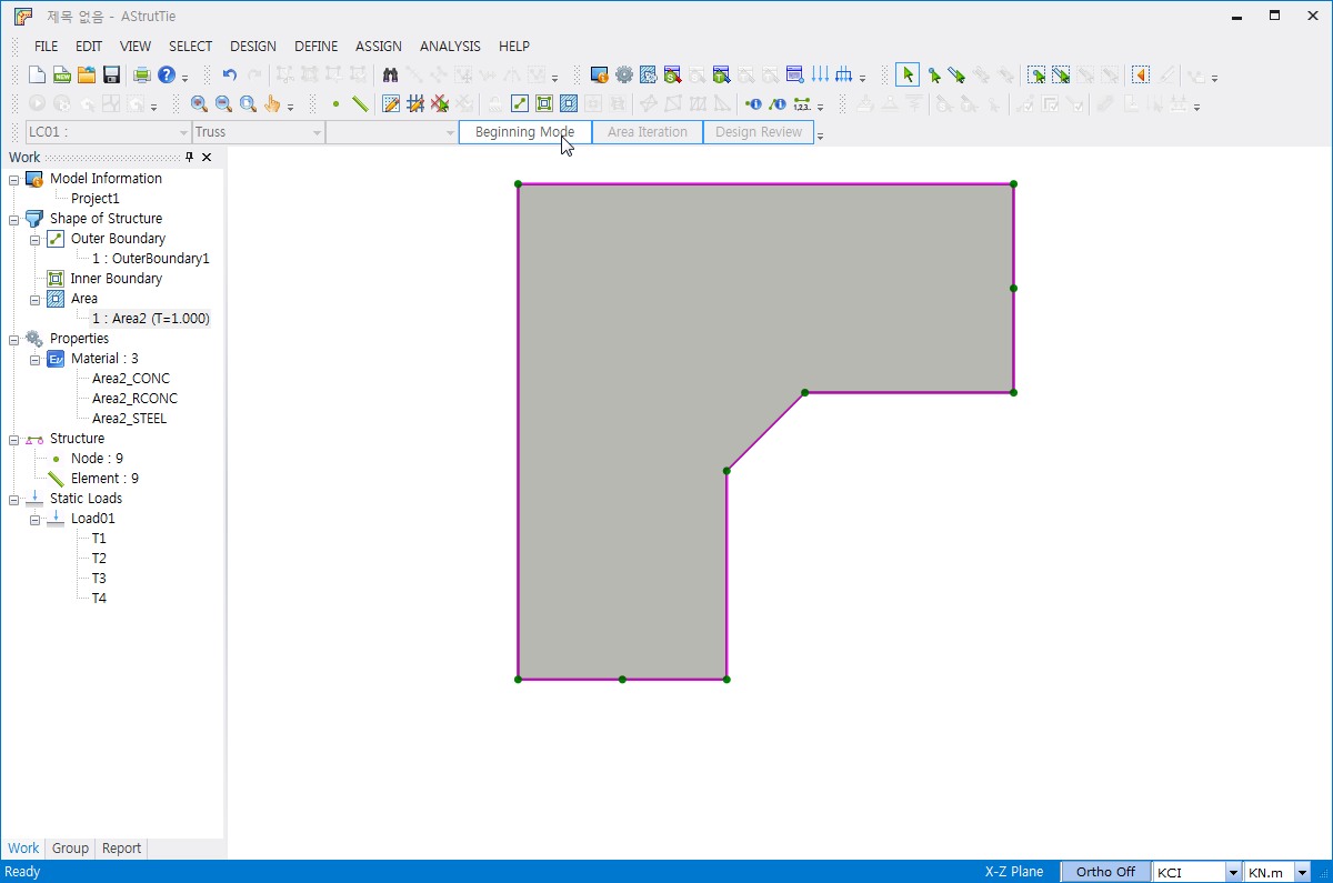
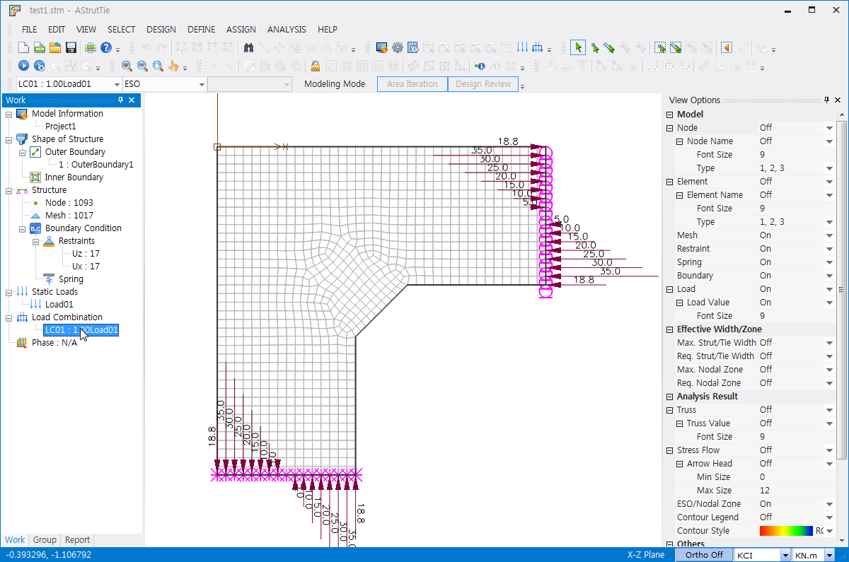
Followings are the figures that illustrate the finite element modeling of a concrete member. After clicking Beginning Mode and selecting Modeling Mode-Stress Flow, DEFINE-Project Information (Dialog) needs to be activated to alter the mesh size. The loads inserted by clicking Static Load are switched to nodal forces automatically.
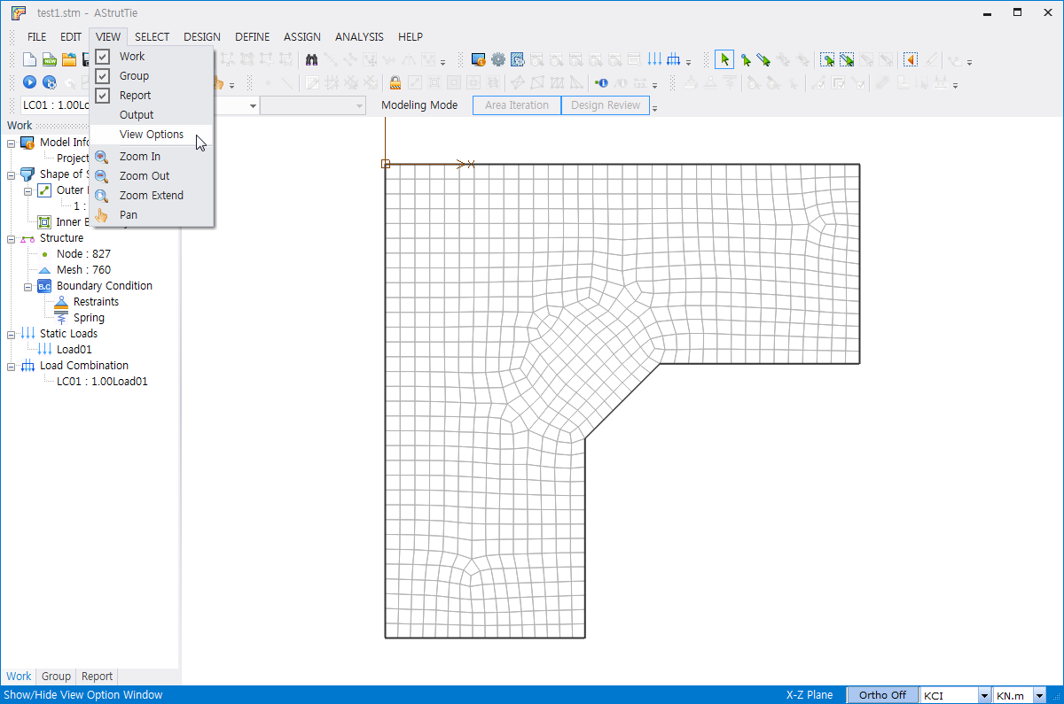
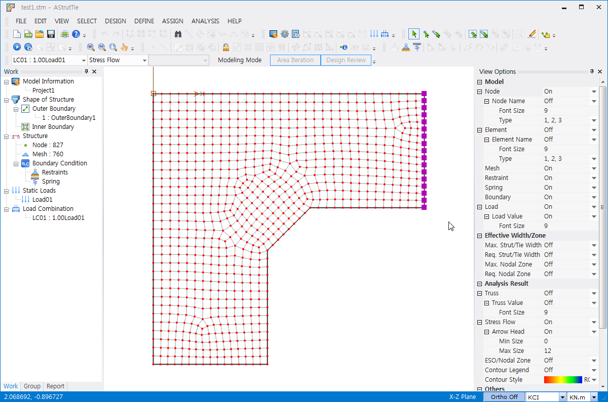
If the mesh size is changed, the boundary conditions must be updated. For this, the View Options Window must be activated and Node must be On, as shown below.
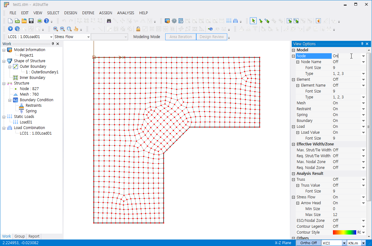
After selecting the nodes on which restraints must be imposed, the boundary conditions are setup by clicking ASSIGN-Restraints.
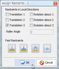
An example is shown below.
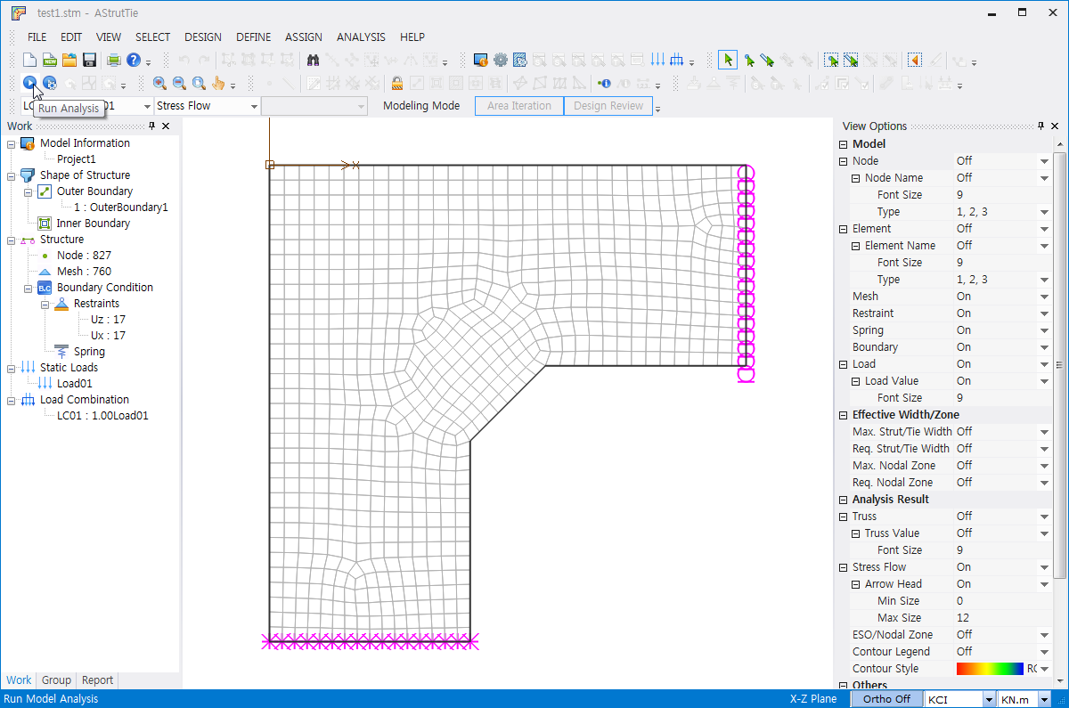
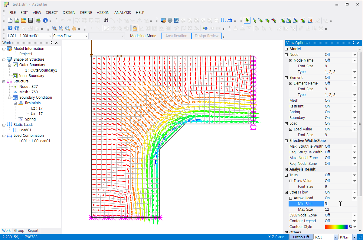
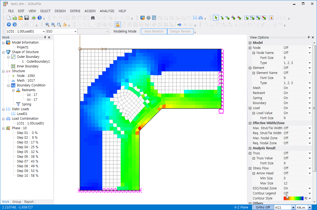
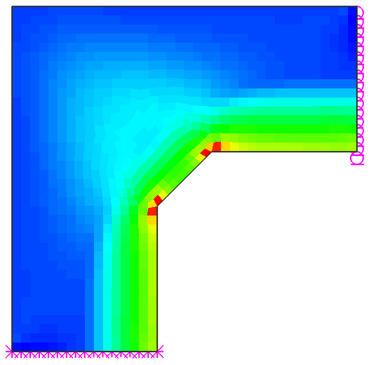
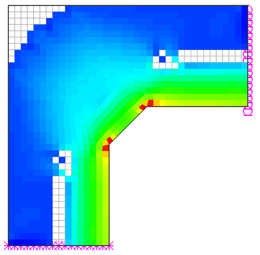
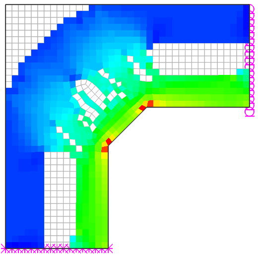
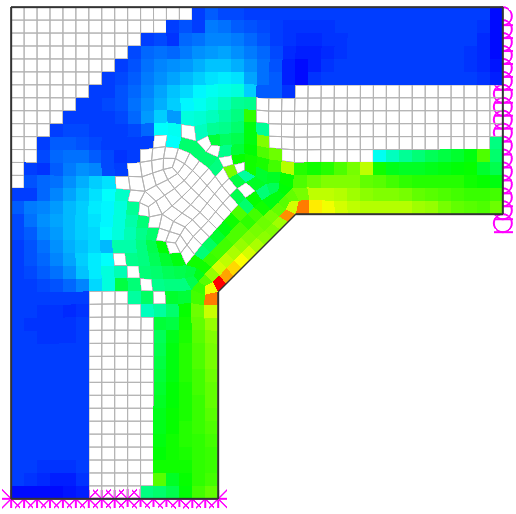
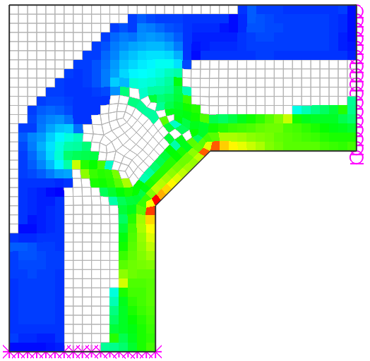
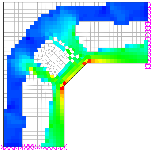
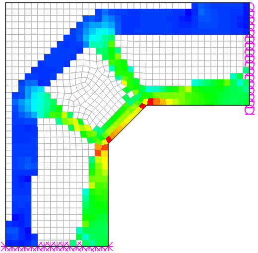
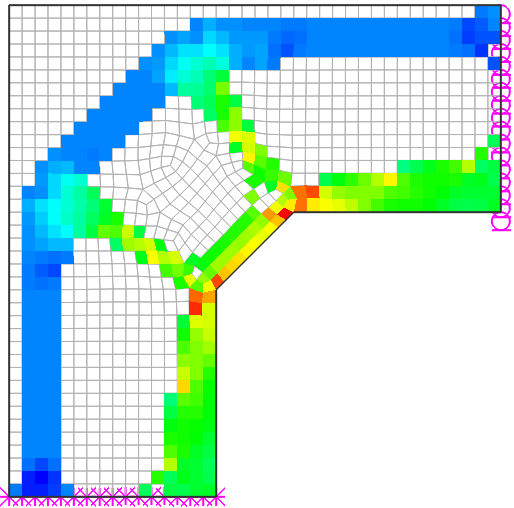
And then, by clicking ANALYSIS-Run Analysis the finite element linear elastic analysis is conducted for checking the compressive principal stress trajectories. The left figure shown below is an example showing the stress trajectories. In the same way, by clicking ESO (instead of Stress Flow) and completing the necessary modifications and inputs in DEFINE-Project Information (Dialog) and ASSIGN-Restraints, the finite element analyses are conducted for checking the approximate load paths by the evolutionary structural optimization technique. The right figure shown below is an example showing the results of the optimization.