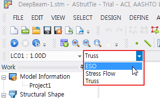
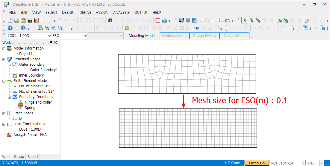
- Select [ESO] - The function is activated only in Professional Version.
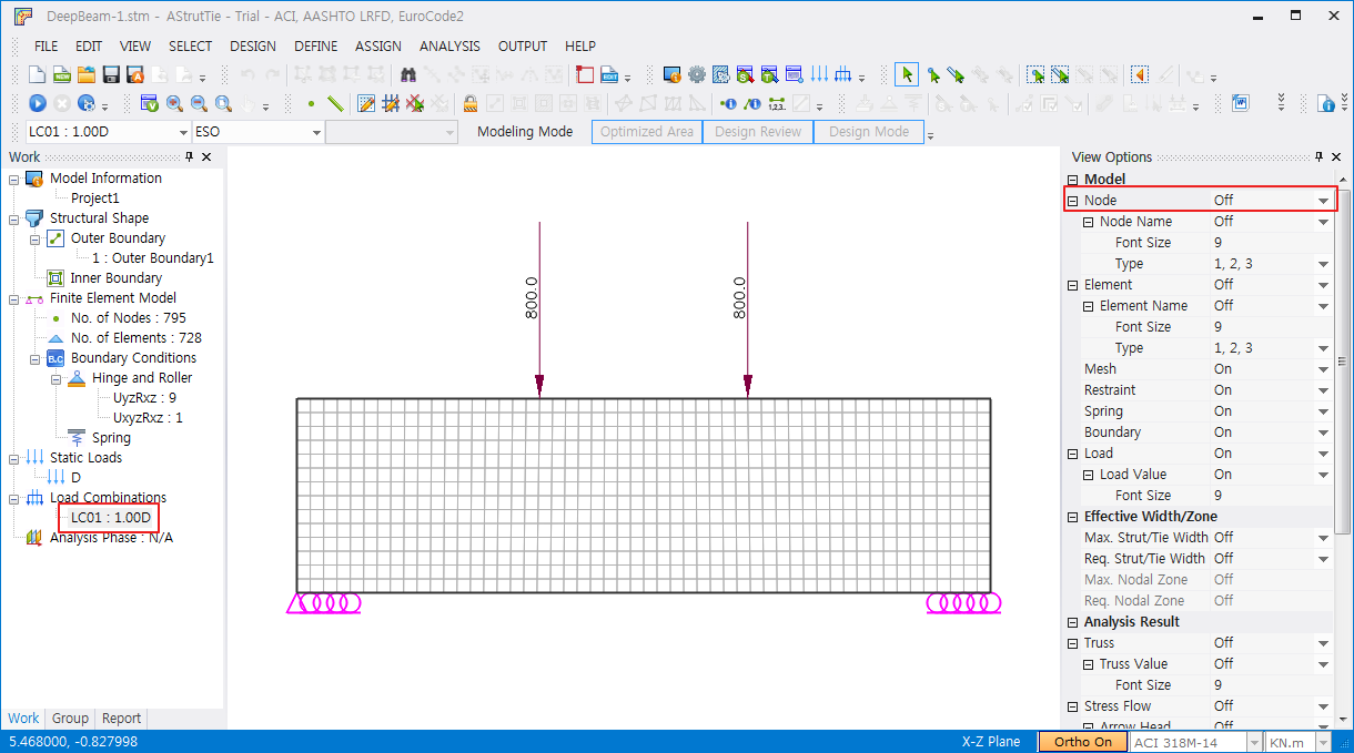
On Work tree, Load Combination : LC01 select to see load and modeling
Select [LC02]
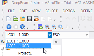
On Work tree, Load Combination : LC02 select to see load and modeling
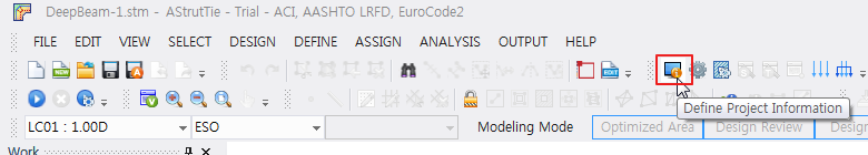
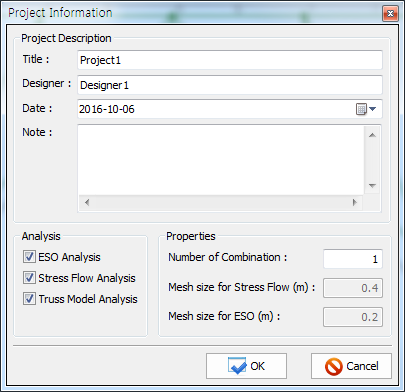
- Click [Project Information]
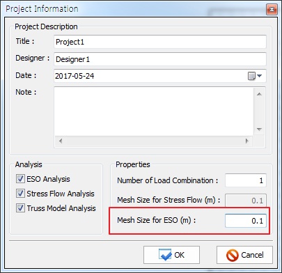
Mesh size for ESO (m) : 0.1
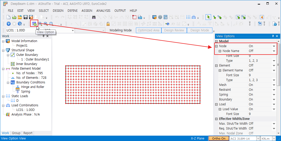
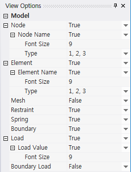
- Click [View Options]
Node – On
Node name – Off
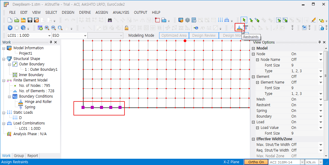
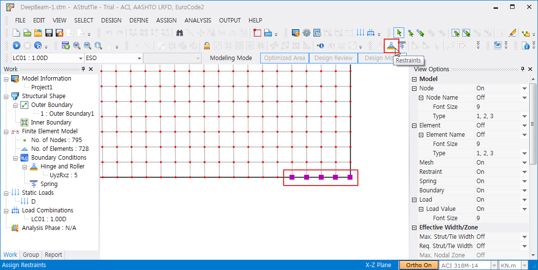
Select 5 nodes on the bottom left
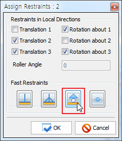
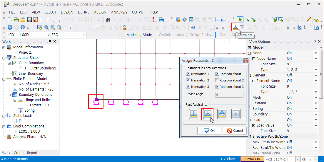
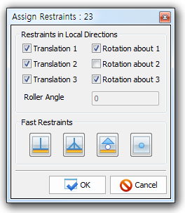
Click [Assign Restraints]
Set roller
Select 5 nodes on the bottom right
Click [Assign Restraints]
Set roller

Select the leftmost joint of the lower part
Click [Assign Restraints]
Set hinge
- Click [View Options]
Node – Off
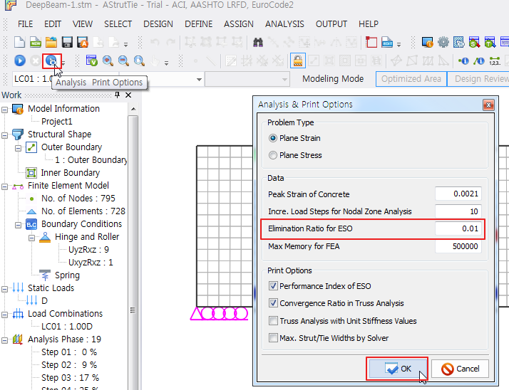
- Click [Analysis, Print Options]
Elimination Ratio for ESO : 0.01 → [OK]
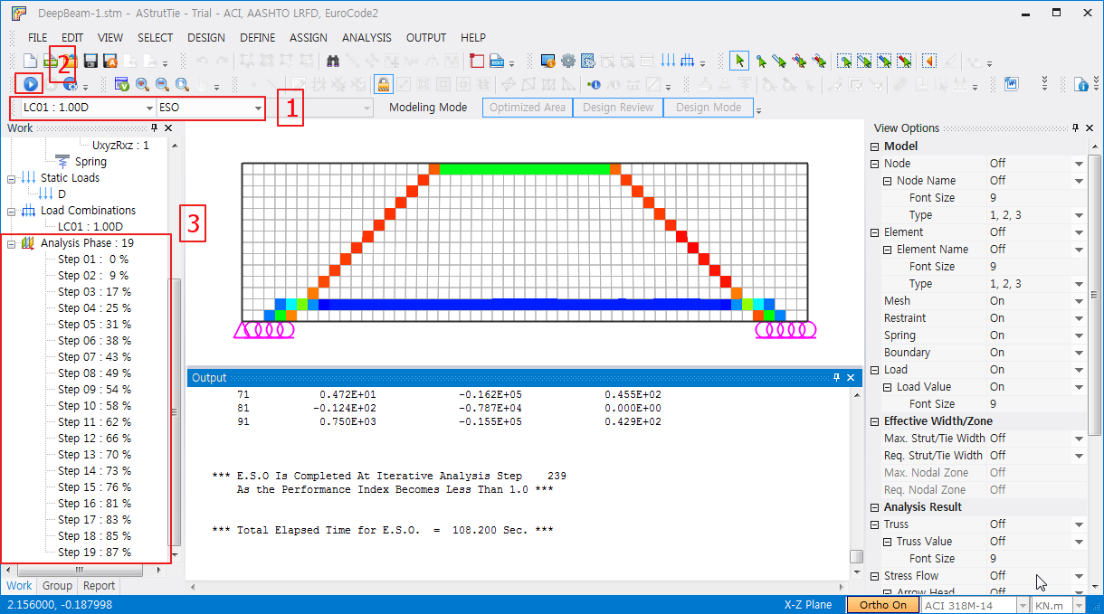
- Choose LoadCase : LC01 - 1
Click [Run Model Analysis] - 2
View ESO analysis result - 3
- Function Reference
Project Information...
The necessary information that must be included in the structural design report including the types of structural analyses (ESO, Stress Flow, Truss), number of load combinations, and mesh sizes for stress flow and ESO analyses are set here. Caution is needed: when a check mark in the analysis box is removed, the corresponding previous modeling information will be deleted.
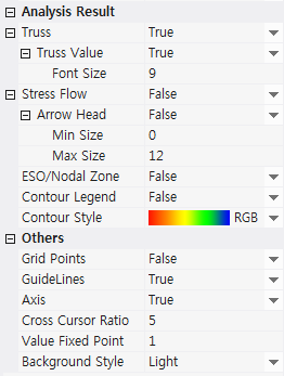
View Options
The View Options Window is (de)activated.
Model
The information on the finite element models for plane solid and truss structures is or is not displayed with variable font sizes and designation methods by clicking True or False in the View Options Window - Model.
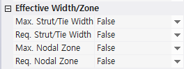
Effective Width/Zone
The available and required widths of struts, ties, and nodal zones are or are not displayed by clicking True or False in the View Options Window – Effective Width/Zone.
Analysis Result
The finite element analysis results including the cross-sectional forces of truss elements, compressive principal stress flows of a concrete member, ESO, and nodal zones are or are not displayed by clicking True or False in the View Options Window – Analysis Result.
Restraints...
The hinge or roller boundary conditions for the finite element analyses of plane solid and truss structures are assigned by this function.
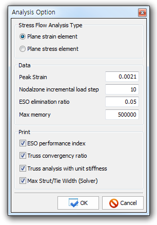
Analysis & Print Options...
The problem type, peak strain of concrete and number of incremental load steps for the finite element material nonlinear analysis of a nodal zone, elimination ratio for the evolutionary structural optimization of a concrete member, and maximum memory for finite element analysis are set by this function. The printing options including the convergence ratio in the iterative finite element analysis of a strut-tie model for determining the cross-sectional areas of struts and ties are set, too. More structural analysis time is required with larger incremental load steps or smaller elimination ratio.
Run Analysis
The executive files for the finite element analyses for ESO, Stress Flow, Truss, and Nodal Zone are activated by this command. During the execution, nothing can be inputted.