The AstrutTie consists of 7 windows as shown below.
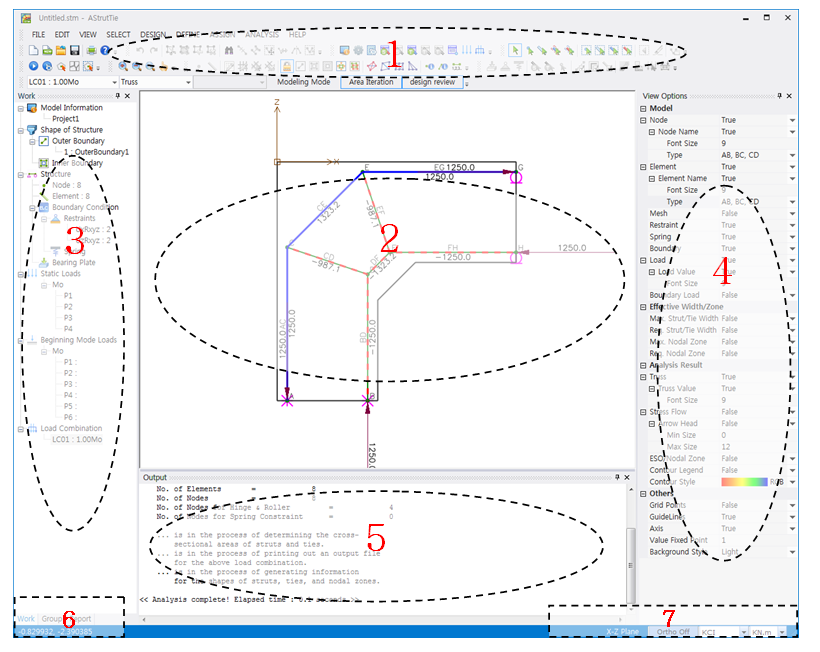
(1) Pull-down Menu & Shortcut Icon Menu Window
Most of the AStrutTie functions can be called in the pull-down menu window. Quick modeling of a concrete member is possible by using shortcut menus of the shortcut icon menu window.
(2) Modeling and Result Display Window
In this window, the finite element models for plane solid and truss structures and their analysis results including compressive principal stress flows, evolutionary structural optimization, and cross-sectional forces of struts and ties are visualized. The structural design report (html, Excel) can be previewed and printed in Report tab.
(3) Tree Menu Window
All types of information on the geometry of concrete member, element and node numbers, boundary and load conditions, and element and node groups are presented in this window. The list of structural design report is also shown.
(4) View Options Window
The view options regarding the finite element models of plane solid and truss structures, structural analysis results, and available widths of strut-tie model elements can be set.
(5) Output Display Window
In this window, the finite element analysis results of plane solid and strut-tie model is displaced in real time.
(6) Tree Menu Tab Window
The transformations of tree menus (Work, Group, Report) are possible.
(7) Design Code & Unit Selection Window
The design code and unit employed in the strut-tie model design are selected in this window.
- Technical Reference
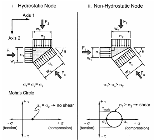
1. Hydrostatic Node versus Non-Hydrostatic Node
For a hydrostatic node, the stress acting on each face of the node is equivalent and perpendicular to the surface of the node.
Because stresses are perpendicular to the faces of hydrostatic nodes, there are no shear stresses acting on the face of a hydrostatic node.
However, achieving hydrostatic nodes for most STM geometric configurations is nearly impossible and usually impractical.
For this reason, most STMs utilize non-hydrostatic nodes. For non-hydrostatic nodes, the ratio of maximum stress on a face of a node to the minimum stress on a face of a node should be less than 2.
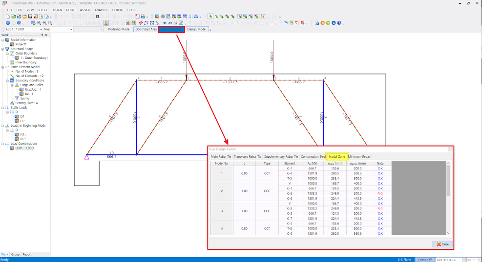
AStrutTie automatically determines nodal zones according to geometry.
Therefore, in most cases, AStrutTie utilize non-hydrostatic nodes.
Although it is not shown graphically, the results of analysis are output as shown below.
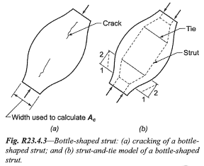
2. Check the bursting of struts and reinforcement for crack control
The check of the bursting of bottle-shaped strut can be performed in two ways.
The first method is to directly modeling the element representing the bursting force as below figure.
The second method is indirect checking method, rather than calculation of the bursting force directly.
For example, ACI 318-14 suggests the reinforcement crossing bottle-shaped struts (Section 23.5).
Through this requirement, determination of reinforcement for crack control can be performed without calculation of bursting force directly.
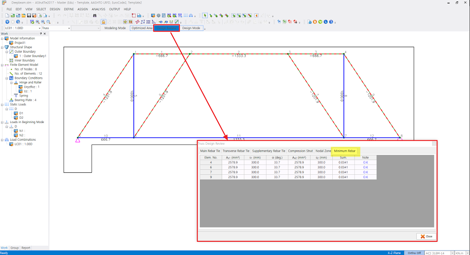
AStrutTie automatically performs the check of minimum reinforcement for crack control only for struts assigned to the ‘Bottle Shape Strut (Satisfying ACI 318M-14 23.5.3)’.
This function is available via [ASSIGN_Strut Types] menu. The results of check for crack control are output as shown below.