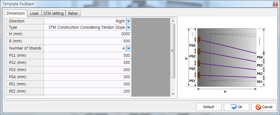
Dimension
The dimensions of a PSC beam anchorage zone with inclined tendons, number of strands, and strand locations are assigned. The boundary lines and tendon layouts are drawn according to the assigned dimensions. The direction Right indicates that the compressive forces of prestressing tendons act from left to right. Two types of strut-tie models are generated: a model constructed by considering the slope of tendons and a model constructed by considering the compressive stress flows. The number of strands is limited to 20. The symbol T is the thickness of the zone.
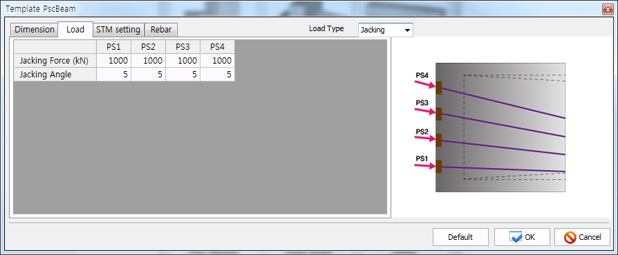
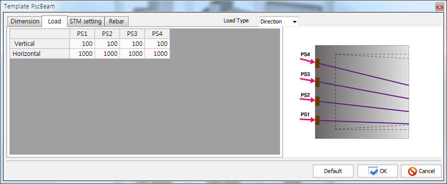
Load
The jacking angle and forces are assigned. The positive values for the jacking forces must be assigned.
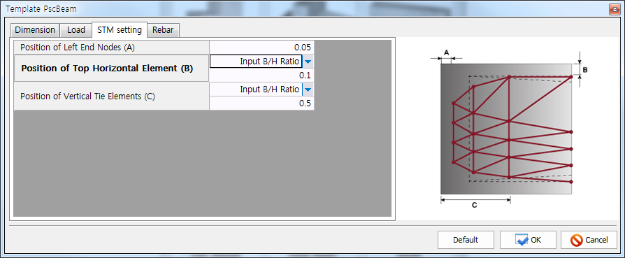
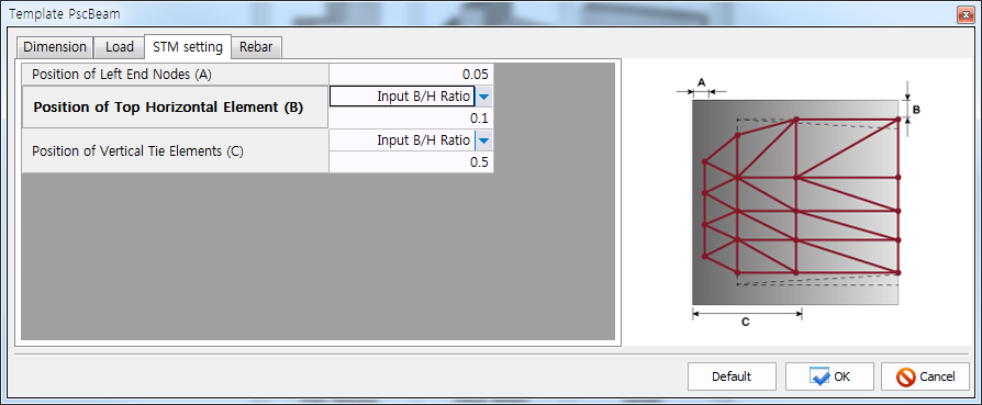
STM setting
Three reference distances A, B, and C are assigned for the automatic construction of the strut-tie model for the anchorage zone with inclined tendons.
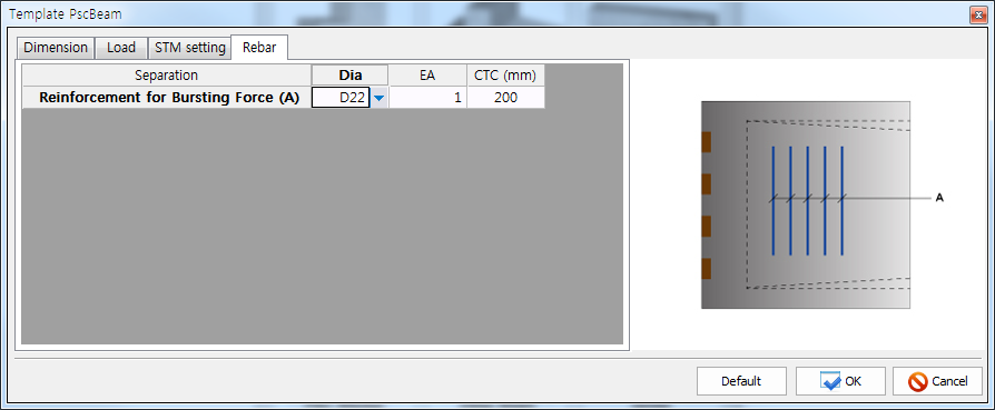
Rebar
The areas of reinforcing bars assigned to the anchorage zone are recognized as the steel tie areas of the strut-tie model for the anchorage zone. The information on the reinforcing bars can be altered, added, or deleted in the DEFINE-Tie Types-Reinforcement Ties. The information can be assigned to the elements of the strut-tie model in the ASSIGN-Tie Types.