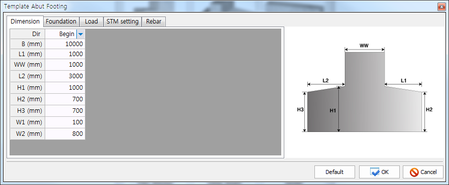
Dimension
The dimensions of an abutment footing are assigned. The boundary lines of the abutment footing are drawn according to the assigned dimensions. The loads and the area of reinforcing bars must be converted to those of the footing with 1 meter thickness since the thickness of the footing is assumed to be 1 meter. The Right in the Dir indicates that the right side of the footing is the front. On the contrary, the Left in the Dir indicates that the left side of the footing is the front. The symbol T used for calculating the soil (or pile) reaction coefficient is the thickness of the footing.
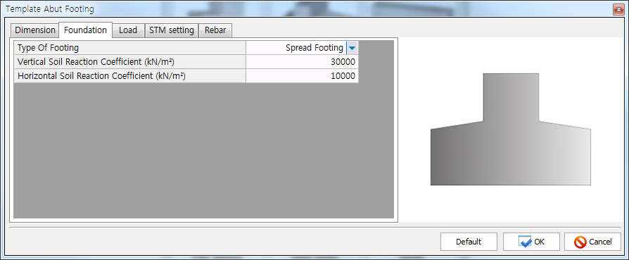
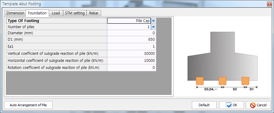
Foundation
The type of abutment footing, coefficients of soil or pile reaction per unit area, and number of piles in two horizontal directions are assigned. Two foundation types (Spread Footing, Pile Footing) are provided.
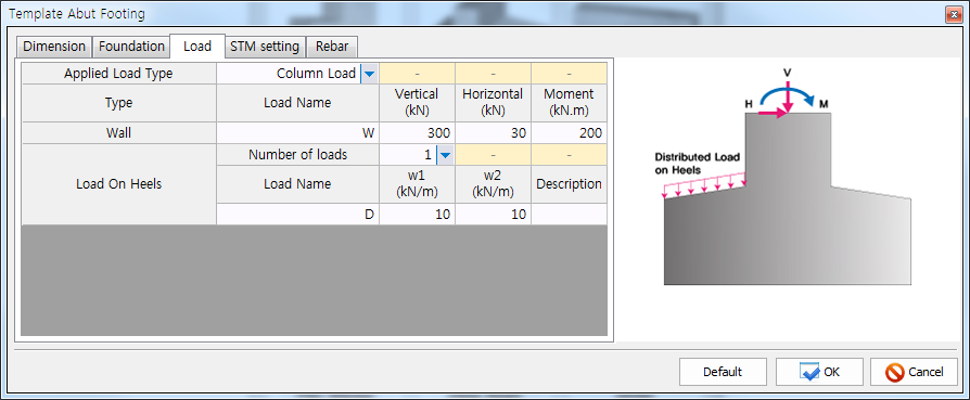
Load
The dead and live loads are assigned. After assigning the load names and description, they can be altered, added, or deleted in the DEFINE-Static Load. The positive values for vertical load, horizontal load, and moment must be assigned.
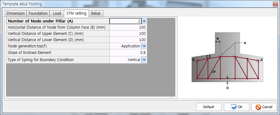
STM setting
The number of nodes below column, three reference distances B, C, and D, and the slope of inclined element are assigned for the automatic construction of a strut-tie model for abutment footing.
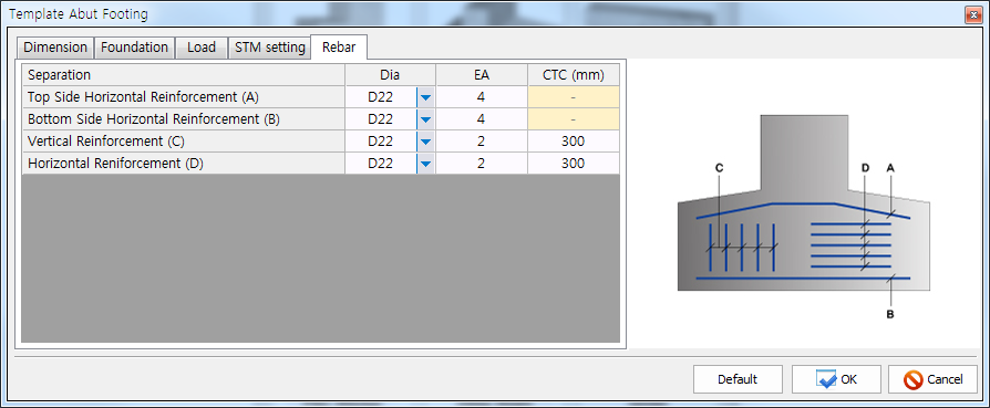
Rebar
The areas of reinforcing bars assigned to the abutment footing below are recognized as the steel tie areas of the strut-tie model for a footing. The information on the reinforcing bars can be altered, added, or deleted in the DEFINE-Tie Types-Reinforcement Ties. The information can be assigned to the elements of the strut-tie model in the ASSIGN-Tie Types.
.